July 23, 2026 at 3:44 pm,
No comments
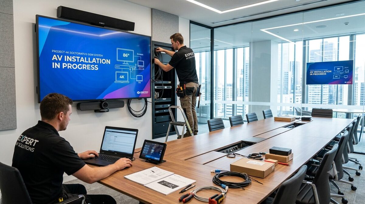
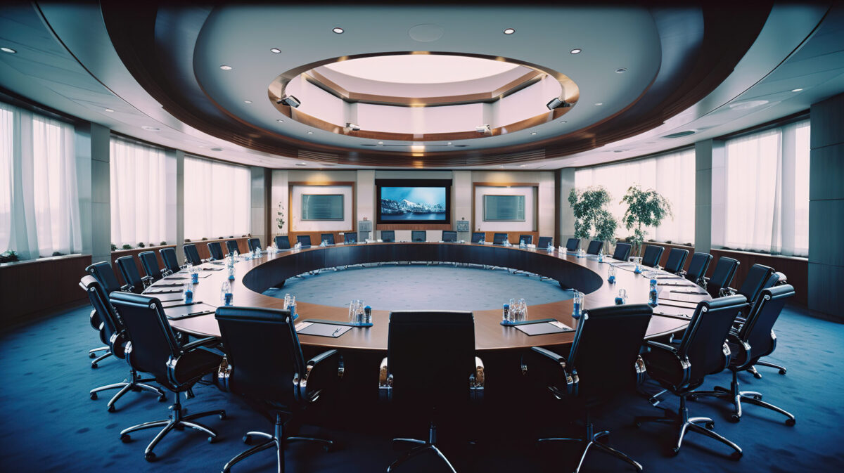
In today’s hybrid work environment, conference room AV installation has become the backbone of effective business communication. Whether you’re an experienced AV system integrator, a consultant, or a system designer, understanding the complexities of conference room av installation is essential for delivering solutions that enhance collaboration, productivity, and user experience.
Conference room av installation involves the strategic planning, design, and deployment of audiovisual equipment to create seamless communication environments. From video conferencing systems and audio DSP processors to display technologies and control systems, every component plays a critical role in ensuring meetings run smoothly without technical disruptions.
The importance of conference room av installation cannot be overstated. According to a 2025 report by AVIXA, 78% of organizations consider high-quality AV systems essential for employee productivity and client engagement (Source: AVIXA Industry Outlook Report 2025). As remote work continues to evolve, businesses are investing more in professional AV
integration services to bridge the gap between in-person and virtual participants.
This comprehensive guide covers everything AV professionals need to know about conference room av installation, from selecting the right equipment to troubleshooting common challenges. Whether you’re designing a small huddle space or a large boardroom AV system, this article provides actionable insights based on 20 years of industry expertise and the latest semantic SEO frameworks.
✓ Conference room AV installation transforms meeting spaces into collaborative hubs with integrated video, audio, and control systems
✓ Proper AV system design requires understanding room acoustics, display placement, and network infrastructure
✓ Modern installations leverage AI-powered automation, wireless presentation systems, and unified communications platforms
✓ Cable management, signal flow optimization, and DSP tuning are critical for professional installations
✓ Regular system commissioning and preventive maintenance ensure long-term performance and ROI
✓ Cloud-based management and remote monitoring are reshaping how AV systems are deployed and maintained
✓ Understanding fire alarm system integration, building codes, and ADA compliance is essential for commercial projects
Conference room AV installation is the professional process of designing, integrating, and deploying audiovisual technology within meeting spaces to facilitate effective communication and collaboration. This encompasses the complete lifecycle from initial site assessment and system architecture to physical installation, programming, calibration, and ongoing support.
At its core, AV installation involves several interconnected disciplines:
System Design and Engineering: Creating detailed technical drawings, rack elevations, and signal flow diagrams that map out every component, connection, and control pathway. This includes load calculations, power distribution planning, and network topology design.
Infrastructure Installation: Running structured cabling (Cat6a, fiber optics), installing conduit pathways, mounting display screens and ceiling microphones, and building equipment racks that house matrix switchers, amplifiers, video processors, and control processors.
Integration and Programming: Connecting disparate AV equipment from multiple manufacturers, writing control system code (Crestron, Extron, AMX), configuring DSP presets, calibrating audio zones, and integrating with building management systems and room scheduling platforms.
Testing and Commissioning: Performing comprehensive system testing, acoustic measurements, video calibration, and end-user training to ensure the installation meets project specifications and client expectations.
Conference room AV installation goes beyond simply mounting screens and speakers. It requires deep technical knowledge of signal processing, network protocols (Dante, AES67, AVB), control architectures, and the ability to troubleshoot complex interoperability issues between video codecs, collaboration platforms (Microsoft Teams, Zoom), and legacy equipment.
Professional AV integrators must also understand electrical codes, fire safety regulations, accessibility standards (ADA Section 508), and best practices for rack building, grounding schemes, and RF interference mitigation.
The strategic value of professional conference room av installation extends far beyond technology deployment. Organizations that invest in properly designed AV systems experience measurable benefits across multiple dimensions:
Enhanced Communication and Collaboration
Modern AV installations eliminate the frustration of technical difficulties that derail meetings. When video conferencing equipment works flawlessly, audio reinforcement is crystal clear, and wireless content sharing happens instantly, participants can focus on meaningful discussion rather than troubleshooting technology. This directly impacts decision-making speed and team cohesion.
Improved Employee Productivity
Research consistently shows that poorly functioning meeting room technology wastes significant time. Professional conference room AV installation ensures meetings start on time, remote participants can fully engage, and presenters can seamlessly share content. The cumulative time savings across an organization translates to substantial productivity gains.
Professional Brand Image
When clients or partners visit your office or join virtual meetings, the quality of your AV infrastructure speaks volumes about your organization’s commitment to excellence. A well-executed conference room av installation creates positive impressions and demonstrates professionalism that can influence business outcomes.
Support for Hybrid Work Models
The shift toward flexible work arrangements has made unified communications technology mission-critical. Professional AV installations create equity between in-room and remote participants through intelligent camera tracking, beamforming microphones, and spatial audio processing that replicates natural conversation dynamics.
Cost Efficiency and ROI
While professional conference room av installation requires upfront investment, it delivers long-term value through reduced downtime, lower maintenance costs, energy efficiency, and extended equipment lifespan. Properly installed systems experience fewer service calls and provide more predictable total cost of ownership.
Compliance and Accessibility
Commercial installations must meet building codes, fire safety standards, and accessibility requirements. Professional AV integrators ensure systems comply with regulations while creating inclusive environments for users with hearing or visual impairments through assistive listening systems and closed captioning integration.
Scalability and Future-Proofing
Thoughtful system architecture accommodates growth and technology evolution. Professional installations include proper network infrastructure, modular signal distribution, and open protocols that allow seamless upgrades without complete system replacement.
A comprehensive conference room AV installation comprises multiple integrated subsystems. Understanding each component and how they work together is fundamental to successful AV integration.
Display Technologies
Video displays serve as the visual focal point of any conference room. Professional installations consider:
Large Format Displays: Commercial-grade LED displays or laser projectors with appropriate screen sizes calculated using the 4:6:8 rule (screen height to viewing distance ratio). 4K resolution or higher ensures content clarity for hybrid meetings.
Touch Displays: Interactive touchscreen monitors for collaborative workspaces, enabling direct annotation and whiteboarding applications.
Video Walls: Multi-panel LED or LCD video walls for command centers, executive boardrooms, or presentation halls requiring large-scale visualization.
Projector Systems: Laser phosphor projectors with appropriate throw ratios, lumens ratings, and mounting configurations for dedicated presentation spaces.
Audio Systems
Professional audio installation ensures every participant hears clearly and is heard:
Microphone Arrays: Ceiling microphones with beamforming technology, gooseneck mics for podiums, or boundary microphones for conference tables. Proper microphone placement based on coverage patterns and pickup ranges is critical.
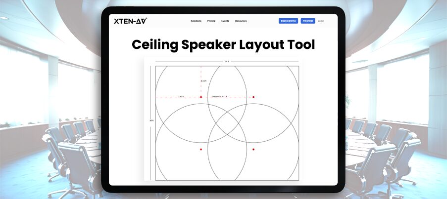
Loudspeakers: Properly positioned ceiling speakers, in-wall speakers, or column arrays that provide even sound pressure level distribution without dead zones or hot spots.
Audio DSP: Digital signal processors that handle acoustic echo cancellation, noise reduction, automatic gain control, ducking, equalization, and routing to ensure intelligible speech.
Amplifiers: Appropriately sized power amplifiers or powered speakers that match impedance and wattage requirements.
Video Conferencing Equipment
The heart of modern collaboration technology:
Video Codecs: Hardware or software-based video conferencing systems (Poly, Cisco, Logitech) that connect to unified communications platforms (Zoom Rooms, Microsoft Teams Rooms, Google Meet).
PTZ Cameras: Pan-tilt-zoom cameras with auto-tracking capabilities that follow active speakers using AI algorithms.
USB Peripherals: All-in-one video bars or modular camera-mic-speaker kits for smaller meeting spaces.
Content Cameras: Dedicated document cameras or downward-facing cameras for capturing physical materials.
Control Systems
User interface devices that simplify operation:
Touch Panels: Wall-mounted or tabletop touchscreen controllers (Crestron, Extron) providing intuitive control of source selection, volume, lighting, and shades.
Button Panels: Simple keypad interfaces for spaces requiring minimal control options.
Mobile Control: Smartphone and tablet apps that allow BYOD control and room booking integration.
Automation: Occupancy sensors and scheduling systems that power equipment on/off based on calendar events.
Signal Distribution
Infrastructure components that route audio and video:
Matrix Switchers: Centralized or distributed video switching and routing platforms that manage multiple sources and destinations.
Scaling and Processing: Video scalers, format converters, and windowing processors that handle resolution matching and multi-image composition.
AV-over-IP: Network-based distribution using Dante, SDVoE, NDI, or proprietary IP protocols for flexible signal routing.
Wireless Presentation: Collaboration gateways (Barco ClickShare, Mersive Solstice) enabling wireless screen sharing from laptops and mobile devices.
Network Infrastructure
IT backbone supporting modern AV systems:
Structured Cabling: Cat6a or fiber optic cables providing bandwidth for 4K video and high-channel-count audio.
Network Switches: Managed switches with PoE+ capability, VLAN configuration, QoS policies, and multicast support.
Network Security: Firewall rules, certificate management, and encryption protocols protecting AV endpoints.
Mounting and Furniture
Physical integration elements:
Equipment Racks: Standard 19-inch racks with proper ventilation, power distribution, and cable management.
Display Mounts: Articulating arms, fixed mounts, or ceiling lifts designed for commercial display weights.
Conference Tables: Integrated cable cubby systems, pop-up connectivity boxes, and under-table mounting solutions.
Power Management
Electrical systems ensuring reliable operation:
UPS Systems: Uninterruptible power supplies protecting critical equipment from outages and voltage fluctuations.
Power Conditioning: Voltage regulators and isolation transformers eliminating electrical noise.
Sequential Power: Power sequencers that turn equipment on/off in proper order preventing damage.
Different meeting spaces demand tailored AV solutions. Understanding room typologies helps system designers specify appropriate technology:
Small Huddle Rooms (4-6 People)
Huddle space AV focuses on simplicity and cost-effectiveness:
Display: Single 32-55 inch display or short-throw projector
Audio: USB speakerphone or simple soundbar with integrated microphone
Video: Wide-angle webcam or all-in-one video bar
Control: Wireless presentation dongle or native app-based control
Connectivity: HDMI cable at table, USB-C docking station
Installation Considerations: Minimal infrastructure, plug-and-play systems, wireless connectivity, wall-mounted equipment to preserve table space
Medium Conference Rooms (6-12 People)
Mid-size meeting room AV balances functionality and sophistication:
Display: 55-75 inch commercial display or dual displays for hybrid layouts
Audio: Ceiling microphone array (3-4 elements) with DSP processing, in-ceiling or surface-mount speakers (2-4 channels)
Video: Auto-tracking PTZ camera or dual-camera system (room view + presenter view)
Control: Tabletop touch panel or wireless touch interface
Connectivity: Table connectivity box with HDMI, USB-C, VGA (legacy), wireless presentation system
Installation Considerations: Cable pathways through furniture, proper acoustic treatment, camera positioning for optimal framing, network drops for control and video
Large Conference Rooms (12-20 People)
Enterprise conference room AV requires sophisticated integration:
Display: 80-98 inch display, video wall, or high-lumen projector with motorized screen
Audio: Comprehensive microphone coverage (ceiling array + table mics), multi-zone speakers with DSP zoning
Video: Dual PTZ cameras for room coverage, dedicated content camera
Control: In-wall touch panel with customized UI, wireless mobile control
Connectivity: Multiple HDMI/USB-C inputs at table and lectern, presentation switching
Additional Systems: Room scheduling displays, occupancy sensors, lighting control integration
Installation Considerations: Acoustical analysis, sight line studies, structured cable infrastructure, equipment room or ceiling plenum for rack mounting
Boardrooms and Executive Spaces (20+ People)
Premium boardroom AV delivers highest quality experience:
Display: Large-format video wall (LED or LCD), confidence monitors, annotation displays
Audio: Distributed microphone system (8+ channels), line array speakers or in-ceiling speakers with subwoofers, assistive listening systems
Video: Multi-camera production system with preset positions, video switching, streaming encoder
Control: Integrated control system managing AV, lighting, shades, HVAC, video recording
Connectivity: Comprehensive connectivity including dual redundant systems, backup switchers
Additional Systems: Confidence monitoring, recording and streaming, interpretation systems, voting systems
Installation Considerations: Dedicated equipment room, redundant systems, aesthetic integration (hidden speakers, motorized lifts), acoustic design by certified acoustician, architectural coordination
Training and Multipurpose Rooms
Flexible AV systems that adapt to multiple use cases:
Display: Multiple displays or projectors with independent source selection
Audio: Zoned audio system supporting breakout configurations, wireless microphones for presenters
Video: Movable camera systems or multiple fixed cameras with preset switching
Control: Scene-based control for different room configurations
Additional Systems: Audience response systems, simultaneous interpretation, stage lighting
Installation Considerations: Flexible infrastructure, portable equipment options, multiple AV connection points, modular furniture integration
Specialty Spaces
Unique environments requiring specialized approaches:
Auditoriums: Professional sound reinforcement, theatrical lighting, presentation switching, assisted listening
Video Production Studios: Broadcast-quality cameras, professional audio mixing, lighting grids, video routing infrastructure
Telepresence Suites: Immersive video walls, spatial audio, precise lighting control, architectural acoustics
Command Centers: Video wall controllers, KVM systems, multi-source monitoring, 24/7 reliability design
Step-by-Step Conference Room AV Installation Process
Professional conference room av installation follows a systematic methodology ensuring successful outcomes:
Phase 1: Discovery and Requirements Gathering
Needs Assessment: Conduct stakeholder interviews with IT managers, facilities personnel, and end users. Document use cases, meeting types, participant counts, and technology preferences.
Site Survey: Visit the space to document room dimensions, ceiling heights, window locations, electrical outlets, network access, HVAC systems, acoustical characteristics, and architectural constraints.
Budget Planning: Establish realistic budgets covering equipment, labor, infrastructure, licensing, training, and ongoing support.
Technology Research: Evaluate AV manufacturers, compare product specifications, review compatibility matrices, and assess integration complexity.
Phase 2: System Design and Engineering
Conceptual Design: Create preliminary designs showing equipment locations, display positions, speaker placement, and user interface locations. Develop use case scenarios and workflow diagrams.
Detailed Engineering: Produce comprehensive technical documentation including:
Equipment schedules listing every component with model numbers and quantities
Rack elevations showing physical layout of equipment in racks
Signal flow diagrams mapping video, audio, and control pathways
Cable schedules detailing every cable run with source, destination, length, and type
Network diagrams showing IP addresses, VLAN assignments, and switch port configurations
Electrical plans indicating power requirements, circuit locations, and UPS connections
Acoustic Analysis: Perform reverberation time calculations, assess background noise levels, model speaker coverage patterns, and specify acoustic treatments if needed.
Code Compliance Review: Verify designs meet building codes, fire regulations, ADA requirements, and telecommunications standards.
Value Engineering: Review designs for cost optimization while maintaining performance objectives.
Phase 3: Pre-Installation Planning
Procurement: Order equipment with adequate lead times, verify specifications match design, inspect shipments for damage.
Coordination: Schedule installation around occupancy, coordinate with general contractors, electricians, low-voltage contractors, and IT teams.
Staging: Unpack equipment, label components, pre-build racks, pre-terminate cables, upload firmware updates, and test equipment before field installation.
Permitting: Obtain necessary building permits and schedule required inspections.
Phase 4: Infrastructure Installation
Cable Installation: Pull structured cabling through conduit or plenum spaces, maintain bend radius specifications, properly label all cables, test cable runs with certification equipment (Fluke, Ideal Networks).
Electrical Work: Install dedicated circuits, outlet boxes, and conduit by licensed electricians following NEC requirements.
Mounting: Install display mounts, projector mounts, speaker brackets, equipment racks, and furniture integration components. Ensure proper load-bearing capacity and seismic bracing where required.
Testing: Verify cable runs, test power circuits, confirm network connectivity.
Phase 5: Equipment Installation
Rack Building: Mount equipment in racks with proper vertical spacing for cooling, install cable managers, make all interconnections, implement cable labeling systems.
Device Mounting: Mount displays following manufacturer specifications, install speakers and acoustic panels, position cameras at correct angles and heights, mount touch panels at accessible locations.
Cable Dressing: Route cables neatly using cable ties and velcro straps, avoid tight bends, separate power from signal cables, use cable concealers for exposed runs, ensure cable service loops for future maintenance.
Power-Up: Energize systems gradually, verify proper voltage, check for ground loops or interference, confirm cooling systems function.
Phase 6: System Integration and Programming
Network Configuration: Assign static IP addresses, configure VLAN tagging, set QoS policies, establish firewall rules, implement network security.
Control Programming: Write control system code, create user interfaces, define button functions, program preset recalls, implement conditional logic.
DSP Programming: Configure audio routing matrices, set EQ curves, adjust gain structures, program acoustic echo cancellation, create preset scenes.
Video Processing: Configure scaling parameters, set EDID management, program input/output resolutions, establish switching presets.
Integration: Connect video conferencing platforms, integrate room scheduling systems, link building management systems, enable remote monitoring.
Phase 7: Testing and Commissioning
Functional Testing: Test every input source, verify all output destinations, confirm control functions, validate audio processing, check video quality.
Performance Testing: Measure audio levels with SPL meter, verify microphone coverage, test video conferencing quality, assess wireless performance, check network bandwidth utilization.
User Acceptance Testing: Conduct tests with end users, simulate actual meeting scenarios, gather feedback, make adjustments.
Documentation: Create as-built drawings, produce system operation manuals, document IP addresses and credentials, provide maintenance procedures.
Phase 8: Training and Handoff
User Training: Conduct hands-on sessions covering basic operation, troubleshooting, wireless connectivity, and video conferencing etiquette.
Technical Training: Train IT staff on system administration, remote monitoring, firmware updates, and first-level troubleshooting.
Documentation Delivery: Provide complete project documentation, warranty information, support contact details.
Project Closeout: Obtain sign-off, transfer warranties, schedule follow-up visits.
Even experienced AV integrators encounter obstacles during conference room av installation. Anticipating these challenges improves project outcomes:
Network and IT Integration Issues
Challenge: Network infrastructure inadequate for AV bandwidth requirements, IT security policies blocking AV protocols, VLAN configuration conflicts, insufficient PoE budget.
Solution: Engage IT stakeholders early, conduct network assessments, document bandwidth requirements, establish dedicated AV VLANs, implement QoS policies, upgrade switches if necessary, coordinate firewall rules.
Acoustic Problems
Challenge: Excessive reverberation time, background noise from HVAC systems, sound isolation issues, acoustic echo in video conferencing.
Solution: Perform acoustic measurements, specify appropriate acoustic treatment (absorption panels, bass traps), work with mechanical engineers to address HVAC noise, implement advanced DSP acoustic echo cancellation, adjust microphone placement and gain structure.
Cable Infrastructure Limitations
Challenge: Insufficient cable pathways, distance limitations for copper cables, inability to fish cables through walls, legacy conduit filled to capacity.
Solution: Conduct thorough site surveys, plan cable routes before installation, use fiber optic extenders for long runs, consider AV-over-IP to leverage existing network infrastructure, coordinate with building owners for pathway additions.
Power and Electrical Issues
Challenge: Inadequate electrical circuits, voltage fluctuations, ground loops causing audio hum, insufficient UPS capacity.
Solution: Coordinate with licensed electricians, install dedicated circuits, implement proper grounding schemes, use isolation transformers, specify appropriate UPS systems, install power sequencers.
Room Layout Constraints
Challenge: Obstructions blocking camera views or speaker placement, insufficient wall space for displays, awkward sightlines, columns or beams interfering with equipment.
Solution: Conduct detailed site surveys, create 3D models, coordinate with architects, consider ceiling-mounted solutions, use articulating mounts, plan around constraints during design phase.
Interoperability and Compatibility
Challenge: Manufacturer compatibility issues, firmware conflicts, EDID problems, HDCP handshake failures, legacy equipment integration.
Solution: Thoroughly test equipment combinations before purchase, use EDID managers and video scalers, maintain current firmware versions, implement video processing equipment to handle format conversions, document compatibility matrices.
User Adoption and Change Management
Challenge: Users resist new technology, insufficient training leads to support calls, complexity overwhelms end users, previous system familiarity causes confusion.
Solution: Involve users in design process, create intuitive user interfaces, provide comprehensive training with hands-on practice, create quick reference guides, offer ongoing support, implement progressive disclosure (simple interface with advanced options hidden).
Budget Overruns
Challenge: Scope creep, unexpected site conditions, equipment price increases, additional infrastructure requirements discovered mid-project.
Solution: Conduct thorough site surveys, include contingency budget (10-15%), establish clear change order processes, maintain detailed project tracking, communicate frequently with stakeholders.
Scheduling and Coordination
Challenge: Delays from other trades, occupied spaces limiting installation windows, equipment delivery delays, inspection hold-ups.
Solution: Develop realistic schedules with buffer time, coordinate regularly with all trades, track equipment lead times, schedule installations during off-hours if necessary, maintain open communication with project managers.
Documentation and As-Built Issues
Challenge: Changes made during installation not documented, wiring labels inconsistent or missing, system configuration not recorded, lack of operational documentation.
Solution: Implement field documentation procedures, update drawings in real-time, photograph installations, use cable labeling systems, create comprehensive system documentation, provide operational manuals and training videos.
Professional AV integrators follow established best practices ensuring reliable, maintainable systems:
Design Best Practices
Standardization: Develop room templates for common space types, specify consistent equipment brands and models across the organization, create standardized user interfaces, enabling easier training and support.
Scalability: Design systems with growth capacity, specify modular equipment allowing expansion, provision extra cable pathways and network drops, choose open protocols and standards enabling future integration.
Redundancy: Include backup systems for critical applications, specify dual network paths, implement failover for essential services, provide manual overrides for automated systems.
Accessibility: Ensure controls are reachable from wheelchairs, provide assistive listening systems, integrate closed captioning, use high-contrast user interfaces, follow ADA guidelines.
Energy Efficiency: Implement automatic power management, specify energy-efficient equipment, program standby modes, use occupancy-based control.
Installation Best Practices
Cable Management: Use proper cable ties (velcro, not plastic zip ties on horizontal runs), maintain service loops, avoid crossing power and signal cables, keep cables away from heat sources, label everything clearly.
Grounding: Establish single-point ground, avoid ground loops, use balanced audio connections, separate audio and video grounds when necessary, follow manufacturer grounding recommendations.
Cooling: Provide adequate ventilation in equipment racks, maintain manufacturer-specified clearances, install rack fans if needed, avoid mounting heat-generating equipment adjacent to each other, monitor temperatures.
Cable Testing: Certify all network cables to Cat6a specifications, test HDMI cables at full resolution, verify fiber optic connections with OTDR, document all test results.
Labeling: Label both ends of every cable, use consistent naming conventions, create durable labels, photograph all connections, maintain label databases.
Integration Best Practices
Network Security: Change default passwords, implement VLANs, enable port security, use encryption for remote access, keep firmware updated, disable unused services and ports.
Programming Standards: Write modular code, include detailed comments, use consistent variable naming, implement error handling, create user-friendly feedback messages.
DSP Configuration: Start with manufacturer presets, make incremental adjustments, document all changes, save multiple configuration versions, implement password protection.
System Validation: Test every feature thoroughly, simulate real-world scenarios, verify failover functions, stress-test systems, document performance metrics.
Documentation Best Practices
As-Built Drawings: Update drawings to reflect actual installation, mark all cable routes, document deviations from design, include equipment locations and heights.
System Documentation: Create comprehensive operation manuals, document all IP addresses and credentials, provide wiring diagrams, include troubleshooting flowcharts, maintain version control.
Training Materials: Develop quick start guides, create video tutorials, provide laminated quick references, establish online knowledge bases.
Maintenance Best Practices
Preventive Maintenance: Schedule regular system checks, clean equipment and displays, verify all functions, update firmware systematically, test backup systems.
Remote Monitoring: Implement network monitoring tools, track system health metrics, receive alerts for failures, enable remote troubleshooting, maintain uptime statistics.
Support Processes: Establish clear escalation procedures, maintain spare parts inventory, document common issues and solutions, provide help desk access, schedule periodic training refreshers.
Lifecycle Management: Track equipment age, plan for technology refresh cycles (typically 5-7 years), budget for upgrades, phase out obsolete equipment systematically.
Project Management Best Practices
Communication: Hold regular project meetings, maintain detailed meeting notes, provide status reports, communicate changes promptly, establish clear escalation paths.
Quality Control: Implement inspection checklists, conduct peer reviews of designs, verify equipment before shipment, validate installations at key milestones, obtain stakeholder sign-offs.
Risk Management: Identify potential issues early, develop mitigation strategies, maintain contingency plans, track risks throughout project lifecycle.
Client Relationships: Set realistic expectations, communicate transparently, address concerns promptly, exceed performance commitments when possible, maintain post-installation relationships.

When selecting an AV integration partner for your conference room av installation projects, expertise and proven methodology matter. XTEN-AV brings comprehensive capabilities that ensure successful outcomes:
Deep Technical Expertise
With specialized knowledge in audio DSP programming, video signal processing, network infrastructure, and control system integration, XTEN-AV’s certified engineers deliver solutions that work seamlessly from day one. Our team holds industry certifications including CTS (Certified Technology Specialist), CTS-D (Design), CTS-I (Installation), Dante Level 3, Crestron DMC, and manufacturer-specific credentials.
Proven Methodologies
XTEN-AV follows structured project management approaches based on PMI standards and AVIXA best practices. Every installation progresses through rigorous quality checkpoints ensuring systems meet performance specifications and client expectations.
Comprehensive Services
From initial consultation and system design through installation, programming, commissioning, and ongoing support, XTEN-AV provides end-to-end services. This single-point accountability streamlines projects and ensures consistent quality throughout the technology lifecycle.
Technology Partnerships
Strategic relationships with leading AV manufacturers (Crestron, Extron, Shure, Sennheiser, Sony, Barco, Poly, Cisco) provide access to latest technologies, technical support resources, extended warranties, and competitive pricing that benefits clients.
Industry Experience
Extensive project portfolio spanning corporate boardrooms, educational institutions, healthcare facilities, government agencies, and hospitality venues demonstrates capability to address diverse requirements and complex integration challenges.
Client-Centric Approach
XTEN-AV prioritizes understanding unique business requirements, involving stakeholders throughout the design process, providing comprehensive training, and maintaining responsive support long after installation completion.
Quality Assurance
Rigorous testing protocols verify every system function before client acceptance. Detailed documentation, comprehensive warranties, and ongoing maintenance programs protect client investments.
Innovation Focus
Continuous research into emerging technologies (AI-enhanced video, spatial audio, cloud-based management, IoT integration) ensures clients benefit from forward-looking solutions that anticipate future needs.
Future Trends in Conference Room AV Installation
The AV industry continues rapid evolution driven by technological advancement and changing workplace dynamics. System designers and AV integrators must anticipate emerging trends:
AI and Machine Learning Integration
Artificial intelligence is transforming conference room technology:
Intelligent Framing: AI-powered cameras automatically frame active speakers, adjust composition based on meeting dynamics, and switch between overview and close-up shots without manual intervention.
Voice Recognition: Natural language processing enables voice-controlled meeting room functions, automated transcription services, real-time language translation, and smart assistant integration.
Predictive Analytics: Machine learning algorithms analyze usage patterns, predict equipment failures before they occur, optimize system performance, and provide actionable insights for facility managers.
Audio Enhancement: AI-based noise suppression removes background sounds, enhances speech intelligibility, and creates immersive spatial audio experiences.
Cloud-Based Management and Analytics
Cloud platforms are centralizing AV system management:
Remote Administration: Cloud dashboards enable IT teams to monitor system health, deploy firmware updates, modify configurations, and troubleshoot issues across entire enterprise portfolios from any location.
Usage Analytics: Detailed metrics track room utilization, popular features, technical issues, and user behavior patterns informing space planning and technology investment decisions.
Subscription Models: Software-as-a-service licensing shifts from capital expenses to operational expenses, ensuring systems stay current with regular feature updates.
Increased Network Convergence
AV-over-IP continues displacing traditional point-to-point architectures:
Standards Adoption: SMPTE ST 2110, NDI, SDVoE, and Dante AV provide interoperable protocols enabling flexible signal routing over standard network infrastructure.
Reduced Infrastructure: Centralized equipment rooms replace distributed racks, simplifying maintenance and reducing hardware footprint.
Flexibility: Network-based systems easily adapt to changing requirements through software configuration rather than physical re-cabling.
Enhanced Hybrid Meeting Experiences
Technology addressing hybrid work challenges:
Presence Equity: Intelligent cameras, directional microphones, and spatial audio create experiences where remote participants feel equally present and engaged.
Virtual Collaboration: Digital whiteboards, interactive annotation, and content sharing tools enable seamless collaboration across physical and virtual participants.
Immersive Technologies: Early adoption of holographic displays and virtual reality conferencing creating next-generation meeting experiences.
Sustainability and Green AV
Environmental considerations influencing design decisions:
Energy Efficiency: Low-power components, intelligent power management, and efficient cooling reducing operational costs and carbon footprint.
Lifecycle Management: Focus on repairable, upgradable equipment reducing e-waste and extending useful life.
Sustainable Materials: Preference for manufacturers using recycled materials and responsible supply chains.
Wireless and BYOD Proliferation
Shift toward wireless connectivity:
Wireless Presentation: Continued refinement of wireless collaboration platforms with lower latency, higher resolution support, and better security.
Personal Device Integration: BYOD (Bring Your Own Device) ecosystems where users leverage personal devices as primary collaboration tools.
5G Integration: Emerging 5G networks enabling new use cases for mobile collaboration and remote participation.
Security and Privacy Enhancements
Growing emphasis on protecting sensitive communications:
Encryption: End-to-end encryption for video conferencing streams and control protocols.
Privacy Controls: Physical camera shutters, microphone mute indicators, and clear user notifications when recording.
Compliance: Enhanced features supporting GDPR, HIPAA, and other regulatory requirements for data protection.
Modular and Adaptable Spaces
Physical environments becoming more flexible:
Reconfigurable Rooms: Movable walls, modular furniture, and flexible AV infrastructure enabling spaces that adapt to different meeting types.
Portable Equipment: High-quality portable video conferencing kits complementing fixed installations.
Multi-Purpose Design: Single spaces serving diverse functions from presentations to brainstorming to social gatherings.
Advanced Analytics and Optimization
Data-driven approach to space and technology management:
Occupancy Analytics: Sensor-based tracking identifying underutilized spaces and optimizing real estate investments.
Quality Metrics: Automated collection of audio quality scores, video resolution data, and network performance metrics.
Predictive Maintenance: Analytics identifying patterns preceding equipment failures enabling proactive service.
What is the typical cost of a conference room AV installation?
Conference room AV installation costs vary significantly based on room size, equipment quality, and complexity. A basic huddle room (4-6 people) with all-in-one video bar, single display, and simple connectivity typically ranges $5,000-$10,000. Mid-sized conference rooms (8-12 people) with professional PTZ cameras, DSP audio processing, control systems, and wireless presentation cost $15,000-$35,000. Large boardrooms or specialized spaces can exceed $100,000 when including video walls, multi-camera systems, advanced audio, architectural integration, and custom programming. Installation labor typically represents 20-40% of total project cost depending on complexity and infrastructure requirements.
How long does a conference room AV installation take?
Installation timelines depend on project scope and site conditions. Simple huddle space deployments may complete in 1-2 days including equipment mounting, cabling, and basic configuration. Standard conference rooms typically require 3-5 days for complete installation and commissioning. Complex boardrooms with extensive infrastructure, custom programming, and architectural coordination may take 2-4 weeks. These timelines assume equipment is available and site conditions are favorable. Additional time is required for design, procurement, and user training. Many installations occur in phases to minimize disruption to occupied spaces.
What certifications should I look for in an AV integrator?
Professional AV integrators should hold relevant industry certifications demonstrating technical competency and commitment to best practices. Key certifications include AVIXA CTS (Certified Technology Specialist) demonstrating foundational AV knowledge, CTS-D (Design) for system designers, and CTS-I (Installation) for installation technicians. Manufacturer-specific certifications (Crestron DMC, Extron Control Professional, QSC Q-SYS) indicate expertise with specific platforms. Network certifications (Dante Certification, Cisco CCNA) are valuable for AV-over-IP projects. Project managers should hold PMP or similar credentials. Acoustical consultants should have NCAC or LEED AP certifications for specialized projects.
How often should conference room AV systems be updated?
Technology refresh cycles for AV systems typically range 5-7 years, though this varies by component type. Video codecs and collaboration platforms may require upgrades every 3-5 years to support evolving unified communications standards. Displays can last 7-10 years with proper maintenance. Control systems and audio processors often remain serviceable for 7-10 years with periodic software updates. Rather than complete system replacement, many organizations implement phased upgrades replacing obsolete components while retaining functional infrastructure. Regular preventive maintenance and firmware updates extend equipment life and maintain compatibility with evolving standards. Budget approximately 10-15% of original installation cost annually for maintenance and incremental upgrades.
Can existing AV systems be integrated with new equipment?
Legacy system integration is often possible with proper planning and appropriate interface equipment. Key considerations include signal compatibility (analog vs. digital, resolution support), control protocol compatibility, and network infrastructure adequacy. Video scalers and converters bridge format differences. Control systems may require updated programming to accommodate new devices. Audio DSP systems can often integrate additional microphones or speakers through expansion cards or Dante networking. Thorough assessment of existing equipment capabilities, manufacturer support status, and integration costs versus complete replacement is essential. Sometimes partial upgrades deliver better long-term value than attempting to extend obsolete systems.
What maintenance is required for conference room AV systems?
Preventive maintenance extends system life and ensures reliable operation. Quarterly tasks include display cleaning using approved solutions, lens cleaning on projectors and cameras, filter replacement in projectors, verification of all system functions, and cable inspection for damage. Semi-annual activities include firmware updates, audio calibration checks, control system database backups, and cable connection retightening. Annual maintenance should include comprehensive performance testing, network security audits, acoustic measurements, detailed cleaning of all equipment, and user training refreshers. Implement remote monitoring to identify issues before they affect users. Maintain spare parts inventory for commonly-failed components enabling rapid repairs.
How do you ensure good audio quality in video conferencing?
Exceptional audio quality requires attention to multiple factors throughout design and installation. Start with proper acoustic treatment controlling excessive reverberation and background noise. Select appropriate microphone types (ceiling arrays, gooseneck, boundary) based on room geometry and seating arrangements. Position microphones within manufacturer-specified pickup patterns ensuring even coverage. Implement professional DSP processing with acoustic echo cancellation, noise reduction, and automatic gain control. Specify commercial-grade speakers with even dispersion patterns avoiding feedback zones. Conduct thorough audio testing using real-world scenarios and measurement equipment. Train users on best practices like muting when not speaking and positioning themselves appropriately relative to microphones.
Professional conference room av installation represents a critical investment in organizational collaboration infrastructure. As we’ve explored throughout this comprehensive guide, successful implementations require far more than simply connecting equipment. They demand thorough understanding of acoustical principles, video signal processing, network architecture, control system programming, and the unique requirements of different meeting space typologies.
The shift toward hybrid work models has elevated the importance of properly designed AV systems that create equitable experiences for both in-room and remote participants. Organizations that invest in professional conference room av installation delivered by experienced AV integrators experience measurable improvements in productivity, employee satisfaction, and brand perception.
Key considerations for successful projects include comprehensive needs assessment, detailed system design following semantic SEO frameworks and industry best practices, proper infrastructure installation, sophisticated integration and programming, rigorous testing and commissioning, and ongoing maintenance and support. Understanding common challenges such as network integration issues, acoustic problems, and user adoption barriers enables proactive mitigation strategies.
The AV industry continues rapid evolution with emerging technologies like AI-powered automation, cloud-based management, AV-over-IP distribution, and enhanced hybrid meeting technologies reshaping what’s possible in collaborative spaces. Forward-thinking organizations work with partners like XTEN-AV who stay current with these trends and design scalable systems that accommodate future technological advancement.
A Private Blog Network (PBN) is a collection of websites that are controlled by a single individual or organization and used primarily to build backlinks to a “money site” in order to influence its ranking in search engines such as Google. The core idea behind a PBN is based on the importance of backlinks in Google’s ranking algorithm. Since Google views backlinks as signals of authority and trust, some website owners attempt to artificially create these signals through a controlled network of sites.
In a typical PBN setup, the owner acquires expired or aged domains that already have existing authority, backlinks, and history. These domains are rebuilt with new content and hosted separately, often using different IP addresses, hosting providers, themes, and ownership details to make them appear unrelated. Within the content published on these sites, links are strategically placed that point to the main website the owner wants to rank higher. By doing this, the owner attempts to pass link equity (also known as “link juice”) from the PBN sites to the target website.
The purpose of a PBN is to give the impression that the target website is naturally earning links from multiple independent sources. If done effectively, this can temporarily improve keyword rankings, increase organic visibility, and drive more traffic from search results.


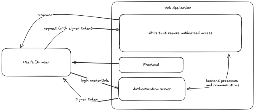
 ) don’t know how to build at least moderately secure authentication into their web applications. JWT provides an easy way to to do this