April 2, 2026 at 10:48 am,
No comments
Creating an efficient coffee shop layout that optimizes both staff workflow and customer flow requires sophisticated planning tools that go beyond basic floor plan software. The most successful cafe floor plans balance operational efficiency with exceptional customer experience, ensuring baristas move seamlessly through their tasks while customers navigate spaces intuitively from entry to exit.
Choosing the best floor plan software specifically designed for workflow optimization and customer flow analysis directly impacts your coffee shop’s profitability, service speed, customer satisfaction, and operational efficiency. Traditional floor planning tools focus on spatial arrangement, but specialized layout software incorporates traffic pattern analysis, queue management, service efficiency metrics, and ergonomic optimization—transforming your coffee shop design from static blueprints into data-driven operational strategies.
The right coffee shop layout software enables you to visualize customer movement patterns, identify bottlenecks before they occur, optimize staff positioning, plan equipment accessibility, and design circulation paths that maximize throughput during peak hours. For modern coffee shops incorporating audio visual systems, digital ordering, and interactive customer experiences, platforms that integrate AV system planning with spatial optimization become essential for creating cohesive, high-performing environments.
This comprehensive guide explores twelve powerful coffee shop layout software platforms specifically selected for their capabilities in workflow design and customer flow optimization. We’ll examine how each platform addresses the unique challenges of cafe operations, with special attention to XTEN-AV X-Draw—the industry-leading solution for AV integrators designing coffee shops where technology, acoustics, and spatial efficiency converge to create exceptional experiences.
What is Coffee Shop Layout Software?
Coffee shop layout software represents specialized digital platforms designed to optimize both the physical arrangement of cafe spaces and the operational workflows that occur within them. Unlike basic floor plan software that merely positions furniture and walls, comprehensive layout software analyzes movement patterns, service sequences, operational efficiency, and customer behavior to create spaces that perform as beautifully as they look.
Core Capabilities of Layout Software
Workflow Optimization Tools: Analyze and optimize staff movement patterns, service sequences, and task completion paths to minimize wasted motion and maximize operational efficiency.
Customer Flow Analysis: Model customer journey maps from entrance through ordering, waiting, pickup, seating, and exit—identifying congestion points, queue management issues, and circulation bottlenecks.
Spatial Planning Features: Create detailed 2D floor plans and 3D models showing equipment placement, furniture arrangements, counter configurations, and circulation aisles with precise measurements.
Performance Metrics: Calculate throughput capacity, service times, seating efficiency, staff productivity metrics, and space utilization ratios based on layout configurations.
Equipment & Ergonomics: Position coffee equipment, POS systems, refrigeration, and preparation areas following ergonomic principles and operational best practices that reduce staff fatigue and improve service speed.
Traffic Simulation: Advanced platforms simulate customer traffic during different time periods and volume scenarios, testing layout effectiveness before physical implementation.
Why Workflow and Customer Flow Matter
Operational Impact: Poor cafe layout design costs businesses 15-30% in lost productivity—baristas walking unnecessary steps, customers confused about ordering procedures, queues forming in inefficient locations.
Customer Experience: Well-designed customer flow reduces perceived wait times, creates intuitive navigation, prevents crowding, and establishes comfortable personal space—directly impacting customer satisfaction and repeat visits.
Revenue Optimization: Optimized layouts increase transaction capacity by 20-40% during peak hours, enabling the same square footage to serve more customers without compromising quality or experience.
Staff Satisfaction: Efficient workflow design reduces physical strain, mental fatigue, and operational stress—improving staff retention and service quality through better working conditions.
For coffee shops incorporating audio visual technology, digital menu boards, ordering kiosks, or background music systems, specialized layout software like XTEN-AV ensures these technical elements integrate seamlessly with operational workflows rather than hindering them.
Key Features and Components for Workflow-Optimized Layout Software
When evaluating coffee shop layout software for workflow and customer flow optimization, prioritize these essential features:
1. Workflow Path Analysis
Digital tools that map staff movement patterns, calculate walking distances, identify repetitive motions, and suggest equipment repositioning to minimize wasted effort and improve service efficiency.
2. Customer Journey Mapping
Visualization of complete customer experience paths—from sidewalk to ordering, payment, waiting, pickup, seating, and exit—with identification of friction points and optimization opportunities.
3. Queue Management Planning
Tools for designing queuing areas, calculating queue capacity, positioning ordering points, and managing customer flow during high-volume periods without lobby congestion.
4. Ergonomic Zone Design
Ergonomic analysis ensuring barista stations, equipment reach distances, and work surface heights follow industry best practices for comfort, safety, and operational speed.
5. Traffic Density Heatmaps
Visual representations showing predicted traffic concentrations at different times of day, helping identify bottlenecks and optimize aisle widths and circulation paths.
6. Service Time Calculations
Performance modeling that estimates service times, throughput capacity, and transaction volumes based on layout configurations, staff positioning, and equipment placement.
7. Multi-Zone Layout Planning
Ability to design distinct functional zones (ordering, preparation, pickup, seating, restrooms) with clear transitions and optimized relationships between zones.
8. Equipment Reach & Clearance
Automated checking of equipment accessibility, maintenance clearances, ADA compliance, and building code requirements ensuring layouts meet regulatory standards.
9. Audio Visual System Integration
For modern cafes with AV technology, specialized tools (like XTEN-AV) for speaker placement optimization, display positioning, cable routing, and system performance aligned with workflow requirements.
10. Seating Optimization
Algorithms that maximize seating capacity while maintaining comfortable personal space, appropriate table sizing, and efficient customer circulation.
11. Staff Positioning Strategy
Tools for determining optimal staff station locations, POS placement, and service area configuration based on customer volume patterns and service model.
12. Simulation & Testing
Advanced platforms offering simulation capabilities that test layouts under various customer volume scenarios, staffing levels, and operational conditions before implementation.
12 Coffee Shop Layout Software Platforms for Workflow and Customer Flow Design
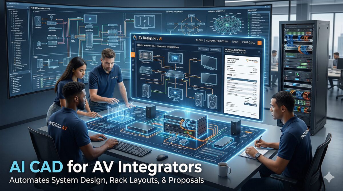
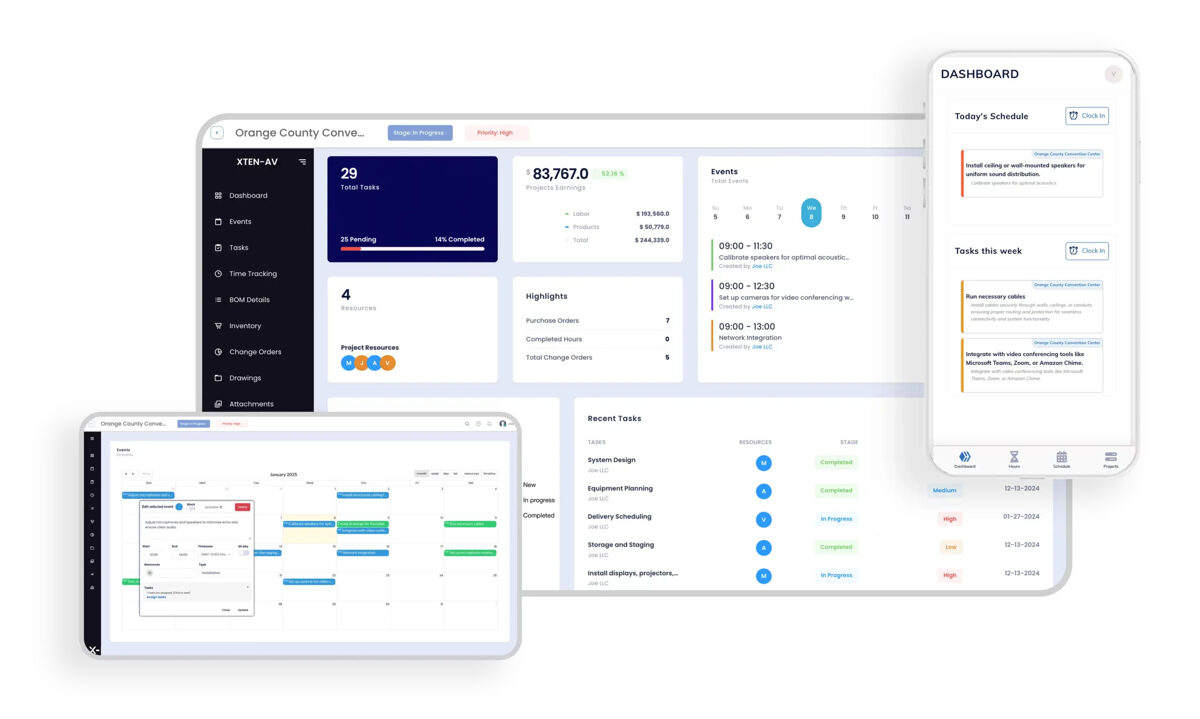
1. XTEN-AV X-Draw – Premier Solution for AV-Integrated Coffee Shop Workflows
For coffee shop designers, AV integrators, and hospitality consultants creating modern cafes where technology, acoustics, and operational efficiency must work in perfect harmony, XTEN-AV X-Draw stands as the best floor plan software for AV companies and forward-thinking cafe operators.
Introduction to XTEN-AV X-Draw
XTEN-AV X-Draw revolutionizes coffee shop layout design by simultaneously optimizing spatial workflows, customer flow patterns, and audio visual system integration in a unified platform. While many layout software solutions address either spatial planning or AV design, XTEN-AV uniquely understands that modern coffee shops succeed when background music coverage, digital signage visibility, ordering technology, and operational workflows function as cohesive systems rather than competing elements.
Originally developed for AV system integrators, XTEN-AV has evolved into a comprehensive workflow optimization platform that analyzes staff movement efficiency, customer journey mapping, and technology integration—making it invaluable for designing high-performing cafe environments where every square foot serves both operational and experiential purposes.
Key Features That Make XTEN-AV Floor Plan Software Stand Out
1. AI-Powered Automated Floor Plan Creation
XTEN-AV eliminates manual drafting by automatically generating accurate floor plans based on room dimensions and inputs. This drastically reduces design time while improving precision and consistency—critical for workflow optimization projects with tight deadlines.
2. AV-Specific Design Intelligence
Unlike generic floor plan tools, XTEN-AV is purpose-built for AV workflows. It understands system layouts, signal flow, and equipment relationships—making it far more relevant for integrators and designers creating coffee shops with integrated audio systems, digital menus, and customer-facing technology.
3. Integrated Equipment Placement Tools
The platform allows you to place displays, speakers, racks, coffee equipment, and other AV components directly into the layout with intelligent positioning. This ensures optimal performance, workflow efficiency, and realistic system visualization for coffee shop environments.
4. Built-In Speaker Layout Optimization
XTEN-AV includes specialized tools for speaker placement, helping designers achieve accurate sound coverage and immersive audio setups without manual calculations—ensuring consistent background music throughout customer areas while maintaining acoustic comfort that supports conversation.
5. Extensive AV Product Library
With access to a massive database of real AV equipment, users can drag-and-drop actual products into their coffee shop floor plans—ensuring compatibility, accuracy, and real-world feasibility for audio visual systems integrated with operational workflows.
6. Automated Cable & Wiring Management
The software intelligently routes cables and manages wiring layouts, reducing errors, preventing signal issues, and improving installation clarity—ensuring technology infrastructure doesn’t interfere with customer circulation or staff workflows.
7. Rack Layout Integration
You can design equipment rack layouts alongside floor plans within the same environment, ensuring seamless coordination between customer-facing cafe design and backend technical infrastructure that supports digital ordering, music systems, and menu displays.
8. Cloud-Based Collaboration
Being fully cloud-based, XTEN-AV enables real-time collaboration across teams. Designers, AV technicians, operations managers, and business owners can access and update coffee shop layouts from anywhere—critical for multi-stakeholder workflow optimization projects.
9. All-in-One AV Workflow Platform
Floor planning is tightly integrated with equipment proposals, BOM (Bill of Materials), and project management tools—eliminating the need to switch between multiple software platforms during coffee shop design and implementation phases.
10. Rapid Design & Layout Generation
What traditionally takes hours can be completed in minutes. Pre-built templates and automation features allow quick creation of professional-grade coffee shop layout designs optimized for both workflow efficiency and customer flow.
11. Seamless CAD & Diagram Integration
XTEN-AV combines floor plans with electrical schematics, signal flow diagrams, and rack elevations in one ecosystem—ensuring consistency across all design documentation shared with contractors, installers, and operations teams.
12. Intelligent Templates & Reusability
Users can create reusable room templates and standardized layouts, making it easy to replicate workflow-optimized designs for multiple coffee shop locations or franchise operations.
13. Real-Time Updates & Accuracy
Any change in equipment, layout, or workflow design automatically reflects across the design, ensuring synchronized and error-free documentation throughout the project lifecycle.
14. Mobile Accessibility for Field Teams
Installation technicians and operations managers can access floor plans and workflow layouts on-site via mobile devices, improving execution accuracy and enabling real-time adjustments during construction and training.
15. High-Quality Visual Documentation
XTEN-AV generates clean, professional floor plans, workflow diagrams, and system documentation that can be directly shared with clients, investors, and operations teams—improving presentation quality and operational clarity.
Workflow-Specific Advantages
-
Staff movement optimization through automated path analysis
-
Service time predictions based on equipment positioning
-
Customer flow simulation showing traffic patterns at peak hours
-
Queue management tools for ordering area design
-
Ergonomic validation ensuring optimal work surface heights and reach distances
-
Technology integration that supports rather than hinders operational efficiency
Pros:
✅ Only platform combining workflow optimization with AV system design
✅ AI automation reduces design time by 70-80%
✅ Cloud-based collaboration for distributed teams
✅ Real-time simulation of customer and staff flows
✅ Integrated equipment specification and BOM generation
✅ Mobile access for field verification
✅ Purpose-built for technology-enhanced cafes
✅ Template standardization for multi-location operations
Cons:
❌ Premium pricing compared to basic layout software
❌ Advanced AV features exceed needs of simple cafes without technology
❌ Requires understanding of AV concepts for full utilization
❌ Overkill for coffee shops without audio visual systems
Best For:
AV integrators, hospitality consultants, and coffee shop operators designing modern cafes with integrated audio systems, digital signage, customer-facing displays, or multi-zone technology. Ideal for businesses prioritizing operational efficiency, customer experience optimization, and technology integration in workflow-driven layouts.

2. SmartDraw – Workflow Diagramming with Floor Planning
SmartDraw excels at combining floor plan creation with workflow diagrams, making it powerful for visualizing both spatial layouts and operational processes in coffee shop environments.
Introduction
SmartDraw’s strength lies in its ability to create floor plans, process flowcharts, and workflow diagrams within the same platform—ideal for coffee shop consultants optimizing both physical space and operational procedures.
Key Features:
-
Intelligent formatting auto-arranging workflow elements
-
Process mapping tools for service sequences
-
Floor plan templates for coffee shop layouts
-
Swimlane diagrams for staff task allocation
-
CAD integration for technical accuracy
-
Microsoft Office compatibility for business workflows
-
Cloud collaboration with team sharing
-
Staff positioning analysis through flowcharting
Pros:
✅ Combines spatial and process design in one platform
✅ Excellent workflow visualization capabilities
✅ Professional flowchart tools for operational planning
✅ Easy collaboration features
✅ Strong template library
✅ Good for both floor plans and operational procedures
Cons:
❌ Limited 3D visualization
❌ No customer flow simulation
❌ Basic traffic analysis capabilities
❌ No AV system integration
❌ Workflow diagrams separate from spatial context
Best For:
Operations consultants, franchise developers, and business analysts needing to document both physical layouts and operational workflows for coffee shop operations and staff training.
3. Flowmap.io – Customer Journey & Traffic Flow Visualization
Flowmap.io specializes in customer journey mapping and traffic flow visualization—complementing traditional floor planning with behavioral analytics.
Introduction
While not a traditional floor plan software, Flowmap.io provides essential customer flow analysis that pairs perfectly with spatial design—helping coffee shop designers understand and optimize customer movement patterns.
Key Features:
-
Customer journey mapping with touchpoint analysis
-
Traffic flow visualization showing movement patterns
-
Heatmap generation for high-traffic zones
-
Service point analysis for queue optimization
-
Path optimization recommendations
-
Data import from foot traffic counters
-
Integration capabilities with other design tools
-
Behavioral analytics for layout refinement
Pros:
✅ Specialized customer flow analysis
✅ Excellent journey mapping visualization
✅ Data-driven insights for layout optimization
✅ Heatmap functionality shows traffic concentration
✅ Integrates with real-world data sources
✅ Focused specifically on customer behavior
Cons:
❌ Not a complete floor planning solution
❌ Requires pairing with spatial design software
❌ No 3D visualization
❌ Limited physical layout tools
❌ Subscription costs for full analytics
Best For:
Customer experience designers, retail consultants, and hospitality planners analyzing traffic patterns and customer behavior to inform coffee shop layout decisions.
4. SketchUp Pro with Flow Extensions – 3D Layout with Workflow Plugins
SketchUp Pro combined with workflow optimization extensions provides powerful 3D modeling with specialized customer flow analysis capabilities.
Introduction
SketchUp’s extensive plugin ecosystem includes flow analysis tools, queue simulators, and traffic modeling extensions that transform it from basic 3D modeling into a comprehensive layout optimization platform.
Key Features:
-
3D modeling for realistic cafe visualization
-
Extension warehouse with flow analysis plugins
-
Traffic simulation extensions (AgentCubes, SketchySim)
-
Ergonomic analysis plugins for workspace design
-
Layout integration for professional documentation
-
VR walkthrough capabilities
-
Animation tools showing customer movement
-
Measurement and analysis features
Pros:
✅ Powerful 3D visualization of layouts
✅ Extensive plugin options for workflow analysis
✅ Strong community and extension support
✅ VR capabilities for immersive presentations
✅ Professional rendering quality
✅ Animation can demonstrate flow patterns
Cons:
❌ Requires multiple extensions for complete workflow tools
❌ Learning curve steeper than specialized platforms
❌ Workflow plugins vary in quality and support
❌ No integrated AV system planning
❌ Plugin costs add to overall expense
Best For:
Architects and designers comfortable with 3D modeling who want to add workflow analysis and customer flow optimization to detailed spatial designs.
5. Floorplanner with Heatmap Analytics – Rapid Layout with Traffic Analysis
Floorplanner offers quick floor plan creation enhanced with heatmap visualization for traffic density and customer flow analysis.
Introduction
Floorplanner’s combination of speed and analytics features makes it practical for coffee shop owners wanting to test multiple layout configurations with traffic flow visualization.
Key Features:
-
Fast floor plan generation
-
Traffic heatmap overlay on designs
-
Customer density predictions
-
Interactive 3D visualization
-
Automated space calculations
-
Quick iteration capabilities
-
Furniture libraries for coffee shops
-
Photo-realistic rendering options
Pros:
✅ Very fast layout creation
✅ Heatmap visualization shows traffic patterns
✅ Easy to test multiple configurations
✅ Affordable pricing for small businesses
✅ Cloud-based accessibility
✅ Good for rapid prototyping
Cons:
❌ Limited workflow analysis depth
❌ Heatmaps based on assumptions, not simulation
❌ No AV planning capabilities
❌ Basic ergonomic analysis
❌ Limited professional features
Best For:
Small coffee shop owners and startup consultants needing quick layout testing with basic traffic flow visualization at affordable price points.
6. Chief Architect with Retail Tools – Professional Architecture with Commercial Features
Chief Architect provides comprehensive architectural design with specialized commercial retail and hospitality tools for detailed workflow planning.
Introduction
Chief Architect’s professional-grade capabilities include commercial kitchen design, retail flow optimization, and building code compliance—ideal for large coffee shop projects requiring complete documentation.
Key Features:
-
Commercial design tools for food service
-
Kitchen workflow planning
-
Building code compliance checking
-
ADA accessibility verification
-
Lighting simulation for ambiance design
-
Traffic flow consideration in planning
-
Construction documentation generation
-
Cost estimation tools
Pros:
✅ Professional architectural precision
✅ Commercial kitchen planning tools
✅ Comprehensive building code checking
✅ Photorealistic rendering
✅ Complete construction documentation
✅ Lighting analysis for customer experience
Cons:
❌ Expensive licensing ($3,000+)
❌ Steep learning curve
❌ Overkill for simple cafe projects
❌ Workflow analysis requires manual planning
❌ No specialized AV tools
Best For:
Architects and design-build firms working on large commercial coffee shops or multi-unit developments requiring full architectural services and permit documentation.
7. RoomSketcher with Traffic Flow Add-on – Visual Design with Movement Analysis
RoomSketcher combines user-friendly floor planning with optional traffic flow analysis features suitable for coffee shop layout optimization.
Introduction
RoomSketcher’s intuitive interface paired with traffic analysis add-ons provides accessible workflow optimization for non-technical coffee shop operators and designers.
Key Features:
-
Drag-and-drop floor planning
-
Traffic flow visualization (add-on feature)
-
360-degree panoramic views
-
Live 3D floor plans
-
Customer path mapping
-
Queue area planning tools
-
Furniture libraries for hospitality
-
High-quality rendering
Pros:
✅ Very user-friendly interface
✅ Traffic flow visualization available
✅ Professional presentation quality
✅ Cloud-based with mobile apps
✅ Good furniture catalogs for cafes
✅ Reasonable pricing
Cons:
❌ Traffic tools are add-ons (extra cost)
❌ Limited workflow analysis depth
❌ No AV integration
❌ Basic simulation capabilities
❌ Export limitations on lower tiers
Best For:
Interior designers and coffee shop consultants needing attractive visualizations with basic customer flow analysis at mid-range price points.
8. AutoCAD with MEP Extensions – Technical Precision for Complex Workflows
AutoCAD enhanced with MEP (Mechanical, Electrical, Plumbing) extensions provides industrial-grade precision for complex coffee shop workflows and systems.
Introduction
For large commercial coffee shops requiring precise utility coordination, equipment specifications, and technical systems integration, AutoCAD with MEP tools delivers unmatched accuracy.
Key Features:
-
CAD precision for exact measurements
-
MEP coordination for utility routing
-
Electrical planning for equipment loads
-
Plumbing integration for coffee equipment
-
HVAC coordination for customer comfort
-
Layered drawings for complex systems
-
Construction documentation
-
Industry-standard file formats
Pros:
✅ Industry-standard professional tool
✅ Extreme precision and accuracy
✅ MEP integration for complete systems
✅ Universal file compatibility
✅ Comprehensive technical capabilities
✅ Professional documentation output
Cons:
❌ Very expensive ($1,775/year)
❌ Steep learning curve (weeks of training)
❌ No customer flow analysis tools
❌ Overkill for most cafe projects
❌ Requires CAD expertise
❌ No workflow optimization features
Best For:
Engineering firms and large commercial contractors working on complex coffee shop buildouts requiring precise technical coordination and construction documentation.
9. Revit with Retail Workflow Plugins – BIM for Operational Planning
Revit with specialized retail workflow plugins brings Building Information Modeling (BIM) precision to coffee shop design and operational planning.
Introduction
Revit’s BIM capabilities enable 3D modeling, system coordination, and operational simulation—ideal for sophisticated coffee shop projects where building systems and workflows must integrate seamlessly.
Key Features:
-
BIM modeling for complete building integration
-
Retail workflow plugins for customer flow
-
Family libraries for coffee equipment
-
Clash detection preventing design conflicts
-
4D scheduling for phased construction
-
Energy analysis for sustainability
-
Collaboration features for large teams
-
Quantity takeoffs for accurate costing
Pros:
✅ Comprehensive BIM capabilities
✅ System coordination prevents conflicts
✅ Workflow plugins available for retail
✅ Professional construction documentation
✅ Strong collaboration features
✅ Energy modeling for sustainability
Cons:
❌ Very expensive ($2,825/year)
❌ Significant learning curve
❌ Overkill for small cafe projects
❌ Requires BIM expertise
❌ Workflow plugins add complexity
❌ Limited customer flow simulation
Best For:
Large architectural firms working on major commercial developments with coffee shops as components of larger buildings requiring full BIM coordination.
10. ViziFlow – Specialized Customer Flow Analysis Platform
ViziFlow focuses exclusively on customer flow optimization and traffic pattern analysis—complementing traditional floor plan software with behavioral insights.
Introduction
ViziFlow specializes in analyzing how customers move through retail and hospitality spaces—providing data-driven insights that optimize coffee shop layouts for maximum efficiency and satisfaction.
Key Features:
-
Customer journey mapping tools
-
Traffic density heatmaps
-
Queue analysis and optimization
-
Dwell time calculations by zone
-
Conversion funnel visualization
-
A/B testing for layout variations
-
Real-world data integration
-
Behavioral prediction algorithms
Pros:
✅ Specialized customer flow expertise
✅ Data-driven optimization recommendations
✅ A/B testing capabilities for layouts
✅ Behavioral analytics integration
✅ Queue optimization tools
✅ Professional consulting services available
Cons:
❌ Not a floor planning tool (requires separate software)
❌ Expensive enterprise pricing
❌ Requires data input for accurate analysis
❌ No 3D visualization
❌ Steep learning curve for analytics
Best For:
Large coffee shop chains and hospitality consultants needing advanced customer behavior analysis and data-driven layout optimization across multiple locations.
11. Space Designer 3D – Quick Layout with Basic Flow Tools
Space Designer 3D offers accessible floor planning with basic traffic flow considerations suitable for small coffee shop projects.
Introduction
Space Designer 3D provides straightforward layout creation with simple traffic analysis—ideal for independent coffee shops and small businesses without complex operational requirements.
Key Features:
-
Browser-based floor planning
-
3D visualization in real-time
-
Basic traffic path overlay
-
Furniture catalogs for hospitality
-
Photo-realistic rendering
-
Measurement tools
-
Quick sharing capabilities
-
Mobile viewing options
Pros:
✅ Very easy to learn and use
✅ Browser-based (no installation)
✅ Real-time 3D preview
✅ Affordable pricing
✅ Basic traffic consideration tools
✅ Good furniture libraries
Cons:
❌ Limited workflow analysis features
❌ Basic traffic tools compared to specialists
❌ No AV planning
❌ Limited professional features
❌ Export options restricted
Best For:
Small coffee shop owners and independent designers needing simple layout tools with basic customer flow considerations at budget-friendly prices.
12. Lucidchart with Process Mapping – Workflow Diagrams Supporting Spatial Plans
Lucidchart excels at process mapping and workflow diagramming—complementing floor plans with detailed operational procedure documentation.
Introduction
While not primarily floor plan software, Lucidchart’s strength in workflow visualization makes it valuable for documenting operational processes that occur within coffee shop layouts.
Key Features:
-
Process flowcharts for service workflows
-
Swimlane diagrams for staff roles
-
Customer journey maps
-
Basic floor plan templates
-
Collaboration features
-
Real-time multi-user editing
-
Integration with business tools
-
Template library for hospitality
Pros:
✅ Excellent workflow documentation
✅ Strong collaboration features
✅ Cloud-based accessibility
✅ Process mapping specialist
✅ Affordable pricing
✅ Good template library
Cons:
❌ Not designed for detailed floor plans
❌ No 3D visualization
❌ Limited spatial design tools
❌ No traffic simulation
❌ Basic furniture libraries
Best For:
Operations managers and training coordinators documenting workflow procedures and service processes to complement floor plans created in dedicated spatial software.
Benefits and Advantages of Workflow-Optimized Layout Software
Investing in specialized coffee shop layout software focused on workflow and customer flow delivers substantial operational and financial benefits:
1. Dramatic Service Speed Improvements
Optimized layouts reduce service times by 20-40% through elimination of wasted staff movement, strategic equipment positioning, and efficient workflow sequences—directly increasing customer throughput during peak hours.
2. Enhanced Customer Experience & Satisfaction
Well-designed customer flow reduces perceived wait times by 30-50% even when actual service times remain constant. Intuitive navigation, comfortable personal space, and logical progression through ordering and pickup areas create positive experiences that drive repeat visits.
3. Increased Revenue Capacity
Workflow-optimized layouts enable the same square footage and staff count to serve 25-40% more customers during rush periods—generating significant revenue increases without proportional cost increases.
4. Reduced Staff Fatigue & Turnover
Ergonomically-designed workspaces and optimized movement patterns reduce physical strain and mental fatigue—improving staff satisfaction, reducing turnover costs (average $3,000-5,000 per employee), and maintaining service quality consistency.
5. Lower Operational Costs
Efficient workflows reduce labor hours required per transaction by 15-25%, translating directly to payroll savings. Better equipment positioning also reduces maintenance costs through improved accessibility.
6. Data-Driven Design Decisions
Traffic simulation and workflow analysis tools provide objective metrics replacing intuition-based layouts—reducing costly redesigns (average $10,000-30,000 for cafe retrofits) through evidence-based planning.
7. Faster Staff Training & Onboarding
Intuitive layouts aligned with natural workflows reduce training time by 30-50%—new baristas reach productivity faster, and operational documentation becomes clearer with visual workflow diagrams.
8. Improved Queue Management
Optimized ordering area design and queue positioning prevents lobby congestion, reduces perceived crowding, and maintains social distancing requirements—particularly important for high-volume locations.
9. Better Technology Integration
For coffee shops with digital ordering, kiosks, payment systems, or AV technology, workflow software (especially XTEN-AV) ensures these elements enhance rather than hinder operational efficiency.
10. Multi-Location Standardization
Template-based workflows enable franchise operations and multi-location chains to replicate successful layouts rapidly—ensuring consistent customer experience and operational performance across locations.
11. Competitive Differentiation
Superior operational efficiency and customer experience resulting from optimized layouts create measurable competitive advantages—particularly in high-competition markets where service speed and atmosphere differentiate brands.
12. Risk Mitigation & Validation
Simulation and testing capabilities identify design flaws before construction—preventing expensive corrections and ensuring layouts perform as intended under real-world conditions.
Step-by-Step Guide: Optimizing Coffee Shop Workflows with Layout Software
Follow this comprehensive methodology to create workflow-optimized and customer flow-enhanced coffee shop layouts:
Step 1: Analyze Current or Planned Operations
For Existing Coffee Shops:
-
Document current workflows with time-motion studies
-
Track customer movement patterns during peak and off-peak hours
-
Interview staff about workflow inefficiencies and physical challenges
-
Measure actual service times at each station
-
Identify bottlenecks, congestion points, and dead spaces
For New Coffee Shops:
-
Define service model (full-service, quick-service, hybrid)
-
Establish menu complexity (affects preparation workflows)
-
Determine volume expectations and peak capacity needs
-
Study successful competitive locations with similar models
-
Create customer personas and journey scenarios
Step 2: Map Service Workflows & Customer Journeys
Staff Workflow Mapping:
-
Document order-to-delivery sequence for each menu item
-
Map equipment interactions (espresso machine → grinder → milk station → assembly)
-
Identify repetitive movements and walking distances
-
Note multi-tasking opportunities and parallel workflows
Customer Journey Mapping:
-
Chart complete customer path (entry → decision → order → payment → wait → pickup → seating → exit)
-
Identify decision points and potential confusion zones
-
Map different customer types (dine-in, grab-and-go, mobile orders)
-
Note touchpoints with staff and technology
Step 3: Select Appropriate Layout Software
Choose based on project complexity:
For Basic Workflows:
For Visual Customer Flow:
For Process Documentation:
For Advanced Analysis:
For AV-Integrated Cafes:
Step 4: Create Base Floor Plan with Zones
-
Input accurate space dimensions
-
Draw walls, structural columns, doors, windows
-
Define primary zones:
-
Mark utility locations (water, gas, electrical panels)
Step 5: Design Service Area Workflow
Equipment Placement:
-
Position espresso machine as workflow anchor point
-
Place grinder within arm’s reach (12-18 inches)
-
Locate refrigeration for minimal walking (under-counter ideal)
-
Position syrups/supplies at point of use
-
Place waste bins at logical disposal points
Staff Movement Optimization:
-
Create linear workflows (order receipt → preparation → assembly → handoff)
-
Minimize crossing paths between baristas
-
Ensure equipment clearances (24-36 inches) for multi-staff operation
-
Position POS systems for clear sight lines to customers
Ergonomic Validation:
-
Verify counter heights (36-42 inches for standing work)
-
Ensure reach distances don’t exceed 24 inches
-
Provide anti-fatigue mat locations
-
Plan sufficient lighting for detail work
Step 6: Design Customer Flow Paths
Entry to Ordering:
-
Create clear sight lines from entrance to menu boards
-
Design queue path that doesn’t block entrance
-
Provide menu viewing opportunity before ordering point
-
Maintain minimum 42-inch aisle width for ADA compliance
Ordering to Pickup:
-
Separate ordering from pickup to prevent congestion
-
Design clear visual cues (signage, floor markings) for movement
-
Provide waiting areas away from active queues
-
Create mobile order pickup zones if applicable
Seating Navigation:
-
Design circulation aisles minimum 36 inches (48 inches ideal)
-
Create logical flow from pickup to seating
-
Avoid dead-end paths requiring backtracking
-
Provide secondary exits for large spaces
Step 7: Integrate Technology & AV Systems (If Applicable)
Using XTEN-AV or similar platforms:
-
Position digital menu boards for visibility from queue
-
Place ordering kiosks to not interfere with traditional queues
-
Design speaker layout for even background music coverage
-
Plan digital display locations for order status
-
Route cables under floors or through walls (never across traffic paths)
-
Position Wi-Fi access points for customer coverage
Step 8: Test with Simulation & Analysis
Software Testing:
-
Run traffic simulations at expected peak volumes
-
Generate heatmaps showing customer density
-
Calculate service time estimates based on workflow paths
-
Test alternative configurations for comparison
Physical Validation:
-
Create full-scale mockups using tape and cardboard if possible
-
Walk through customer journeys physically
-
Simulate staff workflows with timed trials
-
Gather feedback from experienced baristas
Step 9: Refine and Document
-
Address bottlenecks identified in testing
-
Optimize equipment positioning based on simulation results
-
Finalize circulation paths and queue design
-
Generate complete documentation:
Step 10: Create Training Materials
-
Export workflow diagrams for staff training
-
Create station-specific process guides
-
Generate 3D visualizations for pre-opening training
-
Document customer service flows for consistency
-
Prepare troubleshooting guides for peak period management
Comparison Matrix: Choosing the Right Layout Software
Use this comprehensive comparison to select the optimal coffee shop layout software for your specific needs:
Feature Comparison
|
Software
|
Workflow Analysis
|
Customer Flow
|
AV Integration
|
3D Visualization
|
Ease of Use
|
|
XTEN-AV
|
✅✅✅ Advanced
|
✅✅ Good
|
✅✅✅ Excellent
|
✅✅ Good
|
⚠️ Moderate
|
|
SmartDraw
|
✅✅ Good
|
✅ Basic
|
❌ None
|
⚠️ Limited
|
✅✅ Easy
|
|
Flowmap.io
|
⚠️ Limited
|
✅✅✅ Excellent
|
❌ None
|
❌ None
|
⚠️ Moderate
|
|
SketchUp Pro
|
⚠️ Via plugins
|
⚠️ Via plugins
|
⚠️ Manual
|
✅✅✅ Excellent
|
⚠️ Moderate
|
|
Floorplanner
|
⚠️ Basic
|
✅ Good
|
❌ None
|
✅ Good
|
✅✅✅ Very Easy
|
|
Chief Architect
|
✅ Good
|
⚠️ Limited
|
⚠️ Manual
|
✅✅✅ Excellent
|
❌ Complex
|
Pricing & Value Comparison
|
Budget Range
|
Recommended Software
|
Best Value For
|
|
$0-50/month
|
Floorplanner, Space Designer
|
Basic workflow testing
|
|
$50-150/month
|
RoomSketcher, SmartDraw
|
Mid-range visualization
|
|
$150-500/month
|
Flowmap.io, XTEN-AV
|
Advanced analytics and AV
|
|
$500+/month
|
ViziFlow (enterprise)
|
Multi-location optimization
|
|
One-time $300
|
SketchUp Pro
|
Independent designers
|
|
One-time $2,000+
|
Chief Architect, Revit
|
Architecture firms
|
Project Type Recommendations
|
Project Type
|
Primary Software
|
Complementary Tools
|
|
Single Small Cafe
|
Floorplanner or RoomSketcher
|
Lucidchart (workflows)
|
|
High-Volume Quick Service
|
Flowmap.io or SmartDraw
|
SketchUp (visualization)
|
|
Boutique Cafe with AV
|
XTEN-AV X-Draw
|
None needed (all-in-one)
|
|
Multi-Location Chain
|
XTEN-AV or SmartDraw
|
ViziFlow (analytics)
|
|
Restaurant + Cafe
|
Chief Architect
|
SmartDraw (operations)
|
|
Drive-Thru Coffee
|
AutoCAD MEP
|
Flowmap.io (traffic)
|
Decision Framework
Choose XTEN-AV X-Draw if:
-
You’re designing cafes with integrated AV systems
-
Workflow optimization and technology integration are priorities
-
You need all-in-one solution for spatial + technical design
-
Working on multi-location projects requiring standardization
-
Audio visual performance impacts customer experience
Choose SmartDraw if:
-
You need both floor plans and process documentation
-
Workflow diagrams are as important as spatial design
-
Budget-conscious with moderate feature needs
-
Creating training materials from layouts
Choose Flowmap.io/ViziFlow if:
-
Customer behavior data drives your layout decisions
-
Operating multi-location chains needing analytics
-
Have budget for specialized flow analysis
-
Already have basic floor plan software
Choose SketchUp Pro if:
-
3D visualization is your primary requirement
-
Comfortable learning plugin ecosystem
-
Need professional rendering for presentations
-
Want one-time purchase vs. subscription
Choose Floorplanner/RoomSketcher if:
-
Prioritizing ease of use over advanced features
-
Need quick layouts with decent visualization
-
Budget-friendly subscription model preferred
-
Don’t require specialized workflow tools
AI and Future Trends in Workflow Optimization Software
Artificial intelligence and emerging technologies are transforming how coffee shop layouts are designed and optimized:
1. Predictive AI Layout Generation
Next-generation platforms use machine learning trained on thousands of successful cafe layouts to automatically generate optimized designs. Input your space dimensions, service model, and volume targets—AI creates multiple layout options optimized for throughput, customer satisfaction, and staff efficiency.
XTEN-AV’s AI capabilities exemplify this trend, automatically positioning equipment, speakers, and service areas based on best practices and performance data.
2. Real-Time Customer Flow Monitoring
Integration of IoT sensors, camera systems, and Wi-Fi analytics enables live monitoring of customer movements—feeding data back to layout software for continuous optimization. Future systems will automatically suggest layout adjustments based on observed traffic patterns.
3. Digital Twin Simulation
Digital twin technology creates virtual replicas of coffee shops that simulate real-world operations under various conditions—testing staffing levels, menu changes, seasonal variations, and layout modifications before physical implementation.
4. Augmented Reality Layout Testing
AR platforms allow designers and operators to walk through proposed layouts in actual spaces using smartphones or AR glasses—experiencing sight lines, workflow sequences, and customer perspectives before construction begins.
5. Machine Learning Queue Optimization
AI algorithms analyze historical data to predict queue lengths, wait times, and service bottlenecks—dynamically recommending staff positioning, counter configurations, and queue management strategies for different time periods.
6. Automated Ergonomic Analysis
Future software will use biomechanical modeling to analyze staff movements, predict fatigue patterns, and recommend equipment heights, positioning, and workflow sequences that minimize physical strain and maximize long-term operational sustainability.
7. Integrated Occupancy & Density Management
Post-pandemic, layout software increasingly incorporates occupancy monitoring, density calculations, and social distancing planning—ensuring layouts adapt to evolving health requirements and customer comfort expectations.
8. Predictive Maintenance Integration
Smart coffee equipment connected to layout software will predict maintenance needs based on usage patterns—layouts will account for equipment lifespan, service access, and operational redundancy to minimize downtime.
9. Voice-Activated Design Interfaces
Emerging AI assistants will enable voice-controlled layout design—”Move the espresso machine 18 inches left,” “Show me traffic flow at 8am”—accelerating the design process through natural language interaction.
10. Sustainability & Energy Modeling
Advanced platforms analyze how layout decisions impact HVAC efficiency, lighting energy, equipment power consumption, and overall carbon footprint—optimizing for both operational performance and environmental sustainability.
Common Mistakes and Best Practices for Workflow-Optimized Layouts
Avoid these critical errors when designing coffee shop workflows and customer flow:
Critical Workflow Design Mistakes
1. Counter Too Long – Staff Walk Too Far
Mistake: Designing service counters exceeding 12-15 feet, forcing staff to walk excessive distances between equipment and service points.
Solution: Keep primary workflow areas compact (8-12 feet ideal), positioning high-use equipment within 3-step reach of order handoff point.
2. Customer Queue Blocks Entrance
Mistake: Designing queue paths that block entrance doors, preventing incoming traffic and creating congestion.
Solution: Position queue parallel to service counter or in dedicated queue zone offset from main entrance path.
3. Single-Point Bottlenecks
Mistake: Creating layouts where all customers must pass through single choke points (doorways, counters, pickup areas).
Solution: Design multiple flow paths for different customer types (dine-in, grab-and-go, mobile orders).
4. Pickup Area Conflicts with Ordering
Mistake: Positioning order pickup immediately adjacent to ordering counter, causing waiting customers to block ordering queue.
Solution: Separate pickup area by minimum 4-6 feet from ordering point, use clear signage and floor markings.
5. Ignoring Left-Hand/Right-Hand Traffic Patterns
Mistake: Not considering natural traffic flow tendencies (most people turn right upon entering).
Solution: Position menu boards and ordering points aligned with natural flow patterns; test with simulation.
6. Inadequate Staff Clearance
Mistake: Designing workspaces less than 42 inches wide for multi-person operation, causing staff collisions.
Solution: Maintain minimum 48-inch workspaces where multiple baristas work simultaneously; 60 inches for high-volume operations.
7. Equipment Positioned for Aesthetics vs. Workflow
Mistake: Placing espresso machines facing customers for visual appeal despite forcing baristas to turn away during milk steaming.
Solution: Position equipment based on workflow efficiency first, use design elements to create visual interest.
8. No Consideration for Peak vs. Off-Peak
Mistake: Designing layouts optimized only for average traffic, failing during rush periods.
Solution: Design for peak capacity, test layouts at maximum expected volumes using simulation software.
Best Practices for Exceptional Workflows
1. Apply the “Triangle” Principle
Position espresso machine, grinder, and milk station in tight triangle (3-4 feet between points)—minimizing barista movement while maintaining ergonomic comfort.
2. Create Clear Customer Communication
Use floor markings, signage, digital displays, and physical barriers to make customer flow completely intuitive—reducing questions, confusion, and staff interruptions.
3. Design Parallel Workflows
For high-volume cafes, create parallel service lanes enabling multiple baristas to work simultaneously without collision—potentially doubling throughput during peak periods.
4. Plan for Technology Evolution
Design layouts with flexibility for adding kiosks, mobile ordering, robot baristas, or other emerging technologies—use modular configurations that adapt to operational changes.
5. Test with Real-World Scenarios
Use layout software simulation to test:
-
Morning rush (high volume, quick service)
-
Afternoon lull (low volume, complex drinks)
-
Weekend social (high dwell time, seating focus)
-
Staff shift changes (workflow transitions)
6. Incorporate Staff Feedback Early
Involve experienced baristas in layout review before finalizing—their operational knowledge identifies workflow issues invisible in software.
7. Design for Cleaning & Maintenance
Ensure equipment has adequate clearance for daily cleaning and maintenance access—layouts that look good but can’t be properly maintained deteriorate rapidly.
8. Use Software Templates for Standardization
For multi-location operations, create master layouts in software like XTEN-AV or SmartDraw, enabling rapid replication with local adaptations while maintaining core workflow efficiency.
FAQ Section: Coffee Shop Layout Software for Workflow Optimization
What’s the difference between basic floor plan software and workflow optimization platforms?
Basic floor plan software (like Sweet Home 3D or simple RoomSketcher) focuses on spatial arrangement—positioning walls, furniture, and equipment with accurate dimensions and pleasant aesthetics. Workflow optimization platforms (like XTEN-AV, Flowmap.io, or ViziFlow) add operational analysis—calculating service times, simulating customer traffic, optimizing staff movements, and identifying bottlenecks. The former creates visual layouts; the latter creates operationally optimized systems that maximize efficiency and customer experience.
How much can workflow-optimized layouts improve coffee shop performance?
Research and case studies show measurable improvements:
-
Service speed: 20-40% reduction in transaction times
-
Throughput: 25-40% more customers served during peak hours
-
Staff efficiency: 15-30% reduction in steps walked per shift
-
Customer satisfaction: 25-35% reduction in perceived wait times
-
Revenue: 15-25% increase from improved capacity without cost increases
These improvements typically justify software investments within 1-3 months of operation.
Do I need separate software for spatial design and workflow analysis?
It depends on project complexity and budget:
Single Platform (Recommended):
Two-Platform Approach:
-
Spatial: SketchUp, RoomSketcher, or Chief Architect
-
Workflow: Flowmap.io, Lucidchart, or ViziFlow
Single platforms save time and ensure consistency; two-platform approaches offer specialized depth but require data transfer and coordination between tools.
Can workflow software help with staff training and operations manuals?
Absolutely! Most workflow-optimized layout software exports diagrams and documentation that become training materials:
-
Service sequence flowcharts showing step-by-step procedures
-
Station-specific workflows for each barista position
-
Customer journey maps helping staff understand experience
-
Peak period strategies with layout adaptations
-
Troubleshooting guides for congestion management
SmartDraw and Lucidchart particularly excel at creating training-ready documentation from layout designs.
How do I validate that my workflow-optimized layout will actually work?
Validation Methods:
1. Software Simulation (Best):
-
Use platforms with traffic simulation (Flowmap.io, ViziFlow)
-
Run peak period scenarios with expected customer volumes
-
Generate heatmaps showing congestion points
2. Physical Mockups (Most Reliable):
-
Tape out full-scale layouts in warehouse or existing space
-
Conduct timed trials with staff simulating service
-
Walk through customer journeys physically
3. Expert Review:
-
Have experienced cafe operators review layouts
-
Consult with hospitality designers or workflow consultants
-
Compare against successful competitive layouts
4. Pilot Testing (If Possible):
What’s the ROI timeline for investing in workflow optimization software?
Investment: $500-3,000 (software subscription + consultant time)
Typical Returns:
Month 1-3: Layout optimization prevents buildout errors saving $5,000-15,000 in construction corrections
Month 4-12: Operational efficiency improvements:
-
Labor savings: $500-2,000/month from improved productivity
-
Revenue increase: $1,000-5,000/month from higher throughput
Total First-Year Value: $15,000-50,000
ROI: 5x-15x investment
Payback Period: 1-4 months
For multi-location chains, ROI multiplies across locations, often reaching 20x-50x returns.
Do I need technical or design expertise to use workflow optimization software?
Varies by platform:
No Expertise Required:
Moderate Learning (4-8 hours):
-
SmartDraw, Lucidchart (process-focused, business-friendly)
-
XTEN-AV (learning AV concepts takes time, but interface is logical)
Significant Expertise Required:
-
Flowmap.io, ViziFlow (analytics background helpful)
-
SketchUp Pro (3D modeling skills)
-
AutoCAD, Revit (professional training necessary)
Most small business owners succeed with mid-range platforms like SmartDraw or RoomSketcher paired with consultant review for complex workflow analysis.
Can workflow software integrate with coffee shop POS and operations systems?
Integration capabilities vary:
Direct Integration Available:
Export/Import Workflows:
-
Most platforms export layouts to PDF, CAD, images
-
Data can be manually input to operations software
Future Direction:
Currently, most coffee shops use workflow software during design phase, then operate independently—though this is evolving toward continuous optimization models.
Conclusion: Transforming Operations Through Intelligent Layout Design
The difference between average coffee shops and exceptional ones often lies not in coffee quality or aesthetic appeal, but in the invisible operational efficiency and customer flow optimization embedded in their physical layouts. Choosing the best floor plan software that addresses both spatial arrangement and workflow performance represents one of the most impactful decisions in cafe development—affecting every transaction, customer interaction, and operational moment for years to come.
Essential Takeaways:
1. Workflows and Customer Flow Require Specialized Analysis
Basic floor plan software creates visually appealing layouts, but workflow-optimized platforms create operationally superior systems. For high-volume cafes or businesses where efficiency directly impacts profitability, investing in specialized layout software with workflow analysis capabilities delivers measurable ROI within months.
2. Integration Matters More Than Individual Excellence
The best layouts don’t just position equipment well—they create cohesive systems where technology, workflows, and customer experience reinforce each other. Platforms like XTEN-AV X-Draw that integrate AV planning, spatial design, and workflow optimization in unified ecosystems deliver superior results to piecemeal approaches.
3. Test Before You Build
Simulation, heatmap analysis, and physical mockups identify problems costing thousands to fix post-construction. Every dollar invested in workflow validation through software returns 5-10x through prevented errors and optimized operations.
4. Staff Experience Equals Customer Experience
Ergonomic, efficient workflows reduce barista fatigue, improve service consistency, and decrease turnover—directly impacting customer satisfaction. Layout optimization is staff optimization.
5. Technology Integration Requires Specialized Tools
For modern coffee shops incorporating audio visual systems, digital ordering, or interactive technology, generic floor plan software proves insufficient. AV-specific platforms like XTEN-AV ensure technology enhances rather than hinders operational workflows.
Final Recommendations by Priority:
For Operational Efficiency Priority: Primary: XTEN-AV X-Draw or SmartDraw
Why: Integrated workflow analysis with spatial planning
For Customer Experience Focus: Primary: Flowmap.io or ViziFlow + RoomSketcher
Why: Deep customer behavior analytics + attractive visualization
For Budget-Conscious Projects: Primary: SmartDraw or Floorplanner
Why: Affordable platforms with adequate workflow features
For Multi-Location Standardization: Primary: XTEN-AV or SmartDraw
Why: Template systems enabling rapid replication
For AV-Integrated Modern Cafes: Primary: XTEN-AV X-Draw (no close competitor)
Why: Only platform integrating workflows, spatial design, and AV systems
Your Implementation Path:
-
Audit current operations or define service model (2-4 hours)
-
Map workflows and customer journeys (4-8 hours)
-
Select software matching project requirements (review this guide)
-
Create preliminary layouts testing configurations (8-16 hours)
-
Run simulations validating peak performance (4-8 hours)
-
Physical mockup testing if possible (8-16 hours)
-
Finalize design with stakeholder approval (4-8 hours)
-
Generate documentation for construction and training (4-8 hours)
Total investment: 35-70 hours design time + software costs ($500-3,000)
Average savings vs. poor layouts: $15,000-50,000 first year
The coffee shop industry’s competitive intensity demands every operational advantage. While competitors rely on intuition-based layouts, forward-thinking operators leverage data-driven workflow optimization through specialized software—creating measurable performance advantages in service speed, customer satisfaction, and profitability.
Whether you’re launching your first location or optimizing an established chain, the right layout software transforms coffee shop design from artistic guesswork into operational science—where every foot of space, every equipment placement, and every customer touchpoint serves measurable business objectives.
A Private Blog Network (PBN) is a collection of websites that are controlled by a single individual or organization and used primarily to build backlinks to a “money site” in order to influence its ranking in search engines such as Google. The core idea behind a PBN is based on the importance of backlinks in Google’s ranking algorithm. Since Google views backlinks as signals of authority and trust, some website owners attempt to artificially create these signals through a controlled network of sites.
In a typical PBN setup, the owner acquires expired or aged domains that already have existing authority, backlinks, and history. These domains are rebuilt with new content and hosted separately, often using different IP addresses, hosting providers, themes, and ownership details to make them appear unrelated. Within the content published on these sites, links are strategically placed that point to the main website the owner wants to rank higher. By doing this, the owner attempts to pass link equity (also known as “link juice”) from the PBN sites to the target website.
The purpose of a PBN is to give the impression that the target website is naturally earning links from multiple independent sources. If done effectively, this can temporarily improve keyword rankings, increase organic visibility, and drive more traffic from search results.