June 3, 2026 at 1:08 pm,
No comments
What are the best practices for deploying large-scale enterprise AV networks that support thousands of endpoints across multiple buildings while maintaining security, reliability, and performance? The answer: Implement hierarchical three-tier network architecture, deploy functional VLAN segmentation with comprehensive QoS policies, establish redundant infrastructure with automatic failover, integrate AI-powered monitoring and automation, enforce zero-trust security models, and maintain meticulous documentation of all network components—creating a robust foundation that scales seamlessly from hundreds to thousands of collaboration spaces.
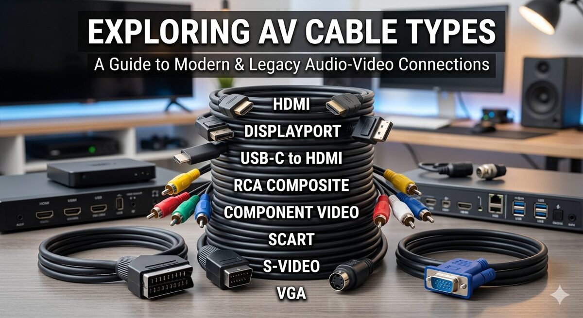
Planning enterprise AV networks shares fundamental principles with residential installations but operates at exponentially greater scale and complexity. Just as a carefully designed ethernet house wiring diagram maps every connection in a home—documenting switch locations, cable runs, patch panel configurations, and device placements—enterprise deployments require comprehensive documentation of network topology, VLAN architecture, IP addressing schemes, routing policies, and security boundaries spanning entire campuses. Understanding Home Network Wiring concepts including structured cabling standards, network hierarchy, traffic segmentation, and bandwidth allocation provides the foundational knowledge necessary for architecting mission-critical AV infrastructure supporting business operations across global organizations.
For AV integrators, enterprise architects, and technology consultants designing large-scale unified communications platforms, success depends on mastering network engineering principles, cybersecurity best practices, automation frameworks, and operational excellence methodologies. This comprehensive guide provides battle-tested strategies, architectural patterns, implementation procedures, and management frameworks for building world-class enterprise AV networks that deliver exceptional user experiences, maintain 99.99% uptime, and adapt seamlessly to evolving business requirements and emerging technologies.
Key Takeaways
-
Enterprise AV networks require three-tier hierarchical architecture (access, distribution, core) supporting 500-10,000+ endpoints
-
Best-practice VLAN design separates traffic by function (video, audio, control, management) improving performance 60-80%
-
Redundancy at every layer with automatic failover ensures 99.99% uptime for business-critical communications
-
Comprehensive QoS policies across all network layers prioritize real-time AV traffic preventing degradation
-
Automation and orchestration reduce deployment time by 70% and configuration errors by 90%
-
Zero-trust security architecture with micro-segmentation reduces breach impact by 80%+
-
AI-powered monitoring detects 85% of potential failures before user impact through predictive analytics
-
Proper bandwidth planning accounts for simultaneous peak usage plus 50-100% growth buffer
-
Multicast optimization through IGMP snooping and PIM reduces bandwidth consumption by 90%
-
Documentation standards are critical—comprehensive records reduce MTTR by 70%
-
Change management processes prevent 95% of human-error outages in production networks
-
Lifecycle planning for 5-7 year technology refresh cycles protects infrastructure investments
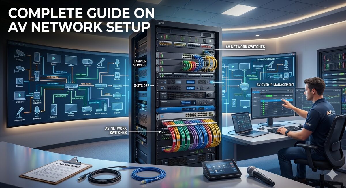
What Is an AV Network Setup?
An AV network setup in enterprise environments is a comprehensive, IP-based infrastructure designed to transport audio signals, video streams, control data, and management traffic for audiovisual systems across converged Ethernet networks using standard networking protocols—replacing traditional point-to-point AV cabling with flexible, scalable, and centrally-managed network-based distribution supporting thousands of simultaneous users.
Defining Large Enterprise AV Networks
Scale Characteristics:
Endpoint Density:
-
500-1,000 endpoints: Mid-size enterprise (50-100 buildings or single large campus)
-
1,000-5,000 endpoints: Large enterprise (multiple campuses, regional offices)
-
5,000-10,000+ endpoints: Global enterprise (worldwide operations, distributed workforce)
Geographic Distribution:
-
Multi-building campuses spanning 100-1,000+ acres
-
Metropolitan deployments across city or region
-
National networks connecting offices nationwide
-
Global infrastructure supporting international operations
Service Complexity:
-
Unified communications: Video conferencing, voice, messaging, presence
-
Collaboration platforms: Wireless presentation, content sharing, whiteboarding
-
Digital workplace: Room scheduling, wayfinding, building automation integration
-
Content distribution: IPTV, digital signage, emergency communications
-
Production facilities: Broadcast studios, training centers, auditoriums
Enterprise AV Network Architecture Layers
Physical Infrastructure Layer:
Structured Cabling System:
-
Horizontal cabling: Cat6a/Cat7 supporting 10GBASE-T to every endpoint
-
Backbone cabling: Single-mode fiber for building-to-building (1-10km)
-
Multimode fiber: OM4 for intra-building distribution (300-550m at 10-100 Gbps)
-
Cable pathways: Conduit, cable trays, risers supporting current and future capacity
-
Patch panels: High-density termination in IDFs/MDFs with comprehensive labeling
-
Testing standards: TIA/EIA-568 certification for all permanent links
Network Equipment:
-
Access switches: 500-2,000 units (24-48 ports each, PoE++, Layer 2/3)
-
Distribution switches: 50-200 units (48-port + uplinks, full Layer 3 routing)
-
Core switches: 4-20 units (chassis-based or fixed, 1-10 Tbps capacity)
-
Wireless infrastructure: Enterprise WiFi 6E/7 for mobile collaboration
-
Network services: DHCP, DNS, NTP, RADIUS, multicast rendezvous points
Logical Architecture Layer:
VLAN Design:
-
50-500 VLANs total across enterprise (depending on segmentation strategy)
-
Functional VLANs: Separate video, audio, control, conferencing, wireless, signage
-
Geographic VLANs: Building or floor-specific when appropriate
-
Security zones: Trusted, semi-trusted, guest, management VLANs
-
Service VLANs: Infrastructure, monitoring, backup, and maintenance networks
IP Addressing Strategy:
-
Private IP space allocation: /8 or /12 for enterprise (10.0.0.0/8 or 172.16.0.0/12)
-
Hierarchical subnetting: Building, floor, function-based address blocks
-
DHCP with reservations: Predictable addressing for known AV devices
-
IPv6 readiness: Dual-stack or IPv6-only for future-proofing
Routing and Switching:
-
Dynamic routing protocols: OSPF, EIGRP, or BGP for scalability
-
Redundant paths: ECMP (Equal-Cost Multi-Path) for load balancing
-
Fast convergence: Sub-second failover with proper tuning
-
Route summarization: Reducing routing table size and update traffic
AV Application Layer:
Video Conferencing Infrastructure:
-
1,000-5,000 conference rooms equipped with AV systems
-
Room systems: Zoom Rooms, Microsoft Teams Rooms, Cisco Webex, Poly
-
Meeting room configurations: Huddle (2-6 people), standard (6-12), large (12-30), boardroom (30+)
-
Hybrid capabilities: In-room and remote participants seamlessly integrated
AV-over-IP Distribution:
-
Encoders/decoders: 2,000-10,000 devices for video distribution
-
Technology mix: SDVoE for low-latency, compressed IP for general use
-
Multicast distribution: One-to-many streaming reducing bandwidth
-
Video walls: Large-format displays in operations centers, lobbies, training facilities
Audio Infrastructure:
-
Dante networking: 5,000-20,000 audio channels distributed
-
DSP processors: Room combining, zoned paging, background music
-
Microphones and speakers: Ceiling arrays, boundary mics, line arrays
-
Emergency communications: Life safety integration with fire alarm systems
Control and Management:
-
Centralized platforms: Crestron Fusion, Extron GlobalViewer, Q-SYS Cloud
-
Room controllers: Touch panels, mobile apps, voice assistants
-
Automation: Scheduling, occupancy-based control, energy management
-
Analytics: Utilization tracking, performance monitoring, ROI reporting
Enterprise vs Traditional AV Infrastructure
Legacy Point-to-Point Model:
-
Dedicated AV cabling: HDMI, SDI, coax for each signal path
-
Matrix switchers: Fixed input/output configurations requiring replacement to scale
-
Isolated systems: Separate networks for AV, IT, building automation
-
Manual management: Configuration, troubleshooting, and changes all manual
-
Limited scalability: Major infrastructure overhaul required for expansion
Modern Network-Based Model:
-
Converged infrastructure: AV, IT, IoT sharing common network
-
Software-defined routing: Any source to any destination via configuration
-
Centralized management: Single pane of glass visibility and control
-
Automated provisioning: New rooms deployed in hours instead of days
-
Unlimited scalability: Add capacity by deploying additional network resources
Why Enterprise AV Network Design Matters
Business Continuity and Productivity
Mission-Critical Communications: Modern enterprises depend on networked AV systems for core operations:
Executive Leadership:
-
All-hands meetings to 10,000+ employees simultaneously
-
Board presentations with confidential financial information
-
Crisis management during emergencies or incidents
-
Investor relations quarterly earnings calls and presentations
Operational Functions:
-
Customer support centers with video assistance
-
Sales presentations to prospects and clients
-
Training delivery to distributed workforce
-
Remote work enablement for hybrid teams
Financial Impact of Downtime:
|
Outage Scope
|
Affected Users
|
Hourly Cost
|
Daily Cost
|
|
Single room
|
5-15
|
$500-1,500
|
$4K-12K
|
|
Floor/building
|
50-500
|
$5K-50K
|
$40K-400K
|
|
Campus-wide
|
500-5,000
|
$50K-500K
|
$400K-4M
|
|
Enterprise-wide
|
5,000-50,000
|
$500K-5M
|
$4M-40M
|
|
Downtime calculations based on:
|
|
|
|
-
Lost productivity: $50-100/hour per affected employee
-
Revenue impact: Failed customer meetings, delayed deals
-
Reputation damage: Client confidence, employee morale
-
Recovery costs: Emergency support, expedited replacements
Security and Compliance Imperatives
Regulatory Requirements:
Healthcare Organizations (HIPAA):
-
Telemedicine platforms require encryption and audit logging
-
Network segmentation separating PHI-handling systems from general network
-
Access controls limiting who can view patient information
-
Business associate agreements covering AV vendors and integrators
Financial Services (PCI-DSS, SOX, GLBA):
-
Trading floor communications must be monitored and recorded
-
Network isolation for cardholder data environments
-
Executive communications require confidentiality protections
-
Audit trails for all access to sensitive financial systems
Education (FERPA):
-
Lecture capture systems handling student educational records
-
Video surveillance integration with campus security
-
Remote learning platforms protecting student privacy
Government and Defense (FISMA, ITAR):
-
Classified information handling in secure conference facilities
-
TEMPEST requirements for electromagnetic shielding
-
Access restrictions based on clearance levels
-
Encryption standards for all communications
Zero-Trust Security Framework:
Micro-Segmentation:
-
VLAN-level isolation for every functional group
-
ACLs enforcing least-privilege access between segments
-
Application-aware firewalling controlling specific traffic types
-
Private VLANs preventing lateral movement within segments
Continuous Verification:
-
802.1X authentication for all devices joining network
-
Certificate-based security replacing static passwords
-
Posture assessment before granting network access
-
Behavioral analytics detecting anomalous activity
Assumed Breach Mentality:
-
Network monitoring on all segments detecting intrusions
-
Automated response quarantining compromised devices instantly
-
Incident response playbooks tested regularly
-
Forensic capabilities for post-incident analysis
Return on Investment and Total Cost of Ownership
Infrastructure Investment:
Capital Expenditure (CapEx):
-
Network infrastructure: $500K-5M (switches, cabling, racks)
-
AV endpoints: $2M-20M (cameras, displays, codecs, processors)
-
Management platforms: $100K-1M (software licenses, servers)
-
Professional services: $500K-3M (design, installation, commissioning)
-
Total initial investment: $3M-29M typical range
Operational Expenditure (OpEx):
-
Support staffing: $300K-3M annually (AV engineers, network admins)
-
Maintenance contracts: $200K-2M annually (vendor support, warranties)
-
Bandwidth costs: $50K-500K annually (Internet, WAN links)
-
Software licensing: $50K-500K annually (management platforms, updates)
-
Total annual operations: $600K-6M typical range
ROI Calculation:
Productivity Gains:
-
Travel reduction: $2M-20M annually (fewer on-site meetings required)
-
Faster decision-making: $1M-10M annually (real-time collaboration across locations)
-
Recruitment advantages: $500K-5M annually (broader talent pool with remote work)
-
Real estate optimization: $1M-10M annually (hoteling, shared spaces vs dedicated offices)
Payback Period: Most enterprise AV networks achieve payback in 18-36 months through combination of productivity gains, travel savings, and real estate optimization.
TCO Over 5 Years:
Example Enterprise (1,000 rooms):
Initial Investment: $10M
Annual Operations: $2M × 5 years = $10M
Technology Refresh (Year 5): $3M
Total 5-Year TCO: $23M
Per-Room TCO: $23,000 over 5 years = $4,600/year/room
Cost Avoidance: Proper design prevents:
-
Rework: 30-40% of project cost if infrastructure undersized
-
Emergency fixes: 5-10x normal cost for after-hours troubleshooting
-
Security breaches: $100K-10M+ per incident average cost
-
Premature replacement: Well-designed systems last 7-10 years vs 3-5 for poor designs
Common Challenges in Large Enterprise AV Installations
Challenge 1: Managing Configuration Complexity at Scale
The Complexity Problem:
Configuration Volume:
-
500-2,000 network switches each requiring configuration
-
5,000-20,000 switch ports with VLAN, QoS, PoE settings
-
1,000-5,000 AV endpoints needing IP addresses, firmware, settings
-
50-500 VLANs propagated across infrastructure
-
1,000+ ACL rules controlling inter-VLAN traffic
Configuration Drift: Without automation, manual changes accumulate:
-
Switch configurations diverge from standards over time
-
VLAN assignments become inconsistent across sites
-
QoS policies applied differently on various switches
-
Security settings weakened by expedient “temporary” changes
-
Documentation becomes outdated and unreliable
Solutions:
Infrastructure as Code (IaC):
Ansible/Terraform Approach:
1. Configuration Templates:
– Switch base configuration
– VLAN definitions
– QoS policies
– ACL rules
– Port configurations by device type
2. Variable Files:
– Site-specific parameters
– IP address allocations
– Device inventories
3. Automated Deployment:
– Push configurations to all switches
– Verify deployment success
– Rollback on errors
4. Version Control:
– Git repository for all configs
– Change tracking and audit trail
– Peer review before deployment
Benefits:
-
Consistency: All switches configured identically
-
Repeatability: Deploy 100 switches as easily as 1
-
Speed: Configure entire building in minutes
-
Validation: Automated testing before production
-
Documentation: Code IS the documentation
Configuration Management Platforms:
-
Cisco DNA Center: Intent-based networking, automated provisioning
-
Aruba Central: Cloud-based management for Aruba infrastructure
-
Ansible Tower/AWX: Open-source automation with enterprise features
-
NetBox: Network documentation and IPAM (IP Address Management)
Challenge 2: Ensuring Consistent QoS Across Multi-Vendor Equipment
Multi-Vendor Environments: Enterprise networks rarely use single vendor:
Typical Vendor Mix:
-
Network switches: Cisco, Aruba, Juniper mixed across sites
-
AV endpoints: Crestron, Extron, Shure, Biamp, various room system vendors
-
Wireless: Cisco, Aruba, Ruckus access points
-
Security: Palo Alto, Fortinet, Cisco firewalls
QoS Inconsistency Problems:
-
DSCP markings: Different defaults per vendor
-
Queue mappings: Varied interpretations of priority levels
-
Trust boundaries: Where to trust/remark packets differs
-
Bandwidth allocation: Different methods and granularity
Solutions:
Standardized QoS Framework:
Step 1: Define Enterprise-Wide Policy
Enterprise QoS Standard:
Traffic Class | DSCP | 802.1p | Queue | BW % | Latency
————–|——|——–|——-|——|——–
Network Control | CS6 | 7 | Q1 | 5% | <1ms
Real-time Audio | EF | 5 | Q2 | 20% | <10ms
Real-time Video | AF41 | 4 | Q3 | 30% | <20ms
Control Systems | AF31 | 3 | Q4 | 10% | <50ms
Wireless Pres | AF21 | 2 | Q5 | 15% | <100ms
Best Effort | DF | 0 | Q6 | 20% | Best effort
Step 2: Configure Trust Boundaries
-
AV devices: Trust DSCP markings from known devices (via 802.1X or MAC list)
-
User devices: Don’t trust; classify and mark at network edge
-
Between switches: Preserve DSCP through trunk links
Step 3: Vendor-Specific Implementation
Cisco Implementation:
– class-map match-any REAL-TIME-AUDIO
– match dscp ef
– policy-map ENTERPRISE-AV-QOS
– class REAL-TIME-AUDIO
– priority percent 20
Aruba Implementation:
– qos dscp-map default
– qos trust dscp
– qos queue-profile ENTERPRISE-AV
Step 4: End-to-End Testing
-
Packet captures verifying DSCP preservation
-
iPerf tests with DSCP marking confirming bandwidth allocation
-
Real AV traffic monitoring during peak usage
-
Regular audits ensuring policy compliance
Challenge 3: Multicast Scalability
Enterprise Multicast Challenges:
Scale Issues:
-
10,000+ multicast groups across enterprise (each AV stream is a group)
-
IGMP state table limitations on switches (512-4,096 groups typically)
-
PIM neighbor relationships consuming CPU on routers
-
Multicast forwarding state memory limitations
-
Rendezvous Point becoming bottleneck
Symptom: Multicast Meltdown
-
AV streams suddenly stop reaching destinations
-
Switch CPU spikes to 100%
-
Network instability affecting all traffic
-
Recovery requires switch reboot, causing broader outage
Solutions:
Multicast Design Best Practices:
IGMP Optimization:
Per-VLAN Configuration:
interface Vlan100
description AV-VIDEO-DISTRIBUTION
ip address 10.100.0.1 255.255.0.0
ip pim sparse-mode
ip igmp version 3
ip igmp snooping querier
ip igmp query-interval 60
ip igmp query-max-response-time 10
ip igmp last-member-query-interval 1000
ip igmp immediate-leave
Source-Specific Multicast (SSM):
-
IGMPv3 required: Supports (S,G) joins instead of (*,G)
-
Eliminates RP: Source-based trees from beginning
-
Address range: 232.0.0.0/8 reserved for SSM
-
Better security: Only specific source can send to group
-
Reduced state: No (*,G) state consuming resources
Anycast RP for Redundancy:
Multiple Rendezvous Points:
RP1 (10.0.0.10) and RP2 (10.0.0.11) both configured as:
ip pim rp-address 10.0.0.100
MSDP peering between RPs:
ip msdp peer 10.0.0.11 connect-source Loopback0
ip msdp originator-id Loopback0
Result: 10.0.0.100 Anycast RP reachable via either RP1 or RP2
Multicast Boundaries:
Prevent Unwanted Propagation:
interface Vlan200
description USER-DATA-NETWORK
ip multicast boundary BLOCK-AV-MULTICAST
ip access-list standard BLOCK-AV-MULTICAST
deny 239.0.0.0 0.255.255.255
permit any
Capacity Planning:
-
Switch selection: Verify multicast group table capacity (4,096+ for AV use)
-
PIM scalability: Distribution layer switches as RPs, not access
-
SSM migration: Move to SSM for large deployments (>1,000 groups)
-
Monitoring: Track multicast state consumption, alert at 70% capacity
Challenge 4: Security at Enterprise Scale
Attack Surface Expansion:
Vulnerable Endpoints:
-
10,000+ AV devices: Many running embedded Linux with rare patches
-
Hundreds of switches: Each a potential pivot point for attackers
-
Unknown devices: Shadow IT AV equipment without IT approval
-
Legacy systems: Equipment no longer receiving security updates
-
Supply chain risks: Compromised devices shipped from factory
Real-World Enterprise Risks:
Botnet Recruitment:
-
Mirai-style attacks: Compromised AV devices participating in DDoS
-
Cryptomining: Stolen CPU cycles from control processors
-
Data exfiltration: Conference room cameras streaming to attackers
-
Lateral movement: Compromised codec used to attack financial systems
Recent Incidents (2024-2026):
-
Fortune 500 manufacturer: Ransomware entered via compromised AV codec
-
Global bank: Unauthorized recording of executive meetings
-
Healthcare system: Patient data accessed via meeting room system
-
University: 5,000 cameras recruited into botnet for DDoS
Solutions:
Zero-Trust Architecture for AV:
Network Micro-Segmentation:
Granular VLAN Strategy:
Instead of: VLAN 100 for all AV (5,000 devices)
Deploy:
– VLAN 100: Executive boardrooms (50 devices)
– VLAN 101: Standard conference rooms Building 1 (200 devices)
– VLAN 102: Standard conference rooms Building 2 (200 devices)
– VLAN 103: Training rooms (100 devices)
– VLAN 104: Digital signage (500 devices)
ACLs between VLANs:
– Deny by default
– Permit only required traffic
– Log all denied traffic
Device Authentication:
802.1X with Certificates:
1. Certificate Authority deployed
2. Each AV device receives unique certificate
3. RADIUS server authenticates via certificate
4. Dynamic VLAN assignment based on device type
5. Periodic re-authentication (every 4-24 hours)
Benefits:
– No shared passwords
– Impossible to spoof device identity
– Automated quarantine of non-compliant devices
– Certificate revocation for compromised devices
Continuous Monitoring:
-
Behavioral analytics: Detect unusual traffic patterns
-
Vulnerability scanning: Weekly automated scans of all AV devices
-
Patch management: Automated firmware updates during maintenance windows
-
Threat intelligence: IoCs (Indicators of Compromise) fed to IDS/IPS
Automated Response:
Security Orchestration:
1. Anomaly Detected:
– Device sending data to unusual destination
– Port scan detected from AV device
– Unauthorized protocol (BitTorrent, IRC)
2. Automated Actions:
– Isolate device to quarantine VLAN
– Alert SOC (Security Operations Center)
– Create incident ticket
– Capture forensic data (packet capture, logs)
– Notify affected business units
3. Investigation and Remediation:
– SOC analyst reviews evidence
– Device reimaged or replaced
– Root cause analysis
– Update prevention measures
Challenge 5: Maintaining Performance During Growth
Capacity Exhaustion:
Common Bottlenecks:
-
Trunk saturation: Uplinks between floors/buildings at 100% utilization
-
Switch oversubscription: Too many ports sharing limited backplane capacity
-
PoE budget depletion: No power available for additional devices
-
DHCP exhaustion: IP address space full
-
Multicast capacity: Tables full, dropping new streams
Symptoms:
-
Video quality degradation: Progressive worsening over weeks/months
-
Inconsistent performance: Some rooms work fine, others struggle
-
Time-based issues: Problems during peak usage (9-11 AM, 1-3 PM)
-
Building-specific: One building affected while others normal
Solutions:
Proactive Capacity Management:
Monitoring and Forecasting:
Monitoring and Forecasting:
Key Metrics to Track:
1. Bandwidth Utilization:
– Per-trunk link utilization (alert at 70%, critical at 85%)
– Per-VLAN bandwidth consumption
– Peak vs average utilization patterns
– Growth rate (month-over-month)
2. Port Density:
– Available ports per switch
– Port utilization percentage
– Projected exhaustion date
3. PoE Budget:
– Total consumption vs capacity
– Per-port draw
– Peak simultaneous usage
– Growth trend
4. IP Address Space:
– Used vs available IPs per VLAN
– Allocation rate
– Projected exhaustion
5. Multicast State:
– Active groups per switch
– Table utilization percentage
– Growth rate
Capacity Planning Process:
Quarterly Capacity Review:
1. Collect Current Metrics:
– Switch port utilization reports
– Bandwidth utilization graphs
– PoE consumption data
– IP address allocation reports
2. Analyze Growth Trends:
– Calculate monthly growth rate
– Project 6-month and 12-month capacity needs
– Identify resource constraints approaching limits
3. Plan Proactive Upgrades:
– Order equipment with 3-6 month lead time
– Schedule installation during maintenance windows
– Budget approval for capital expenditures
4. Document and Communicate:
– Update capacity forecast models
– Report to leadership
– Coordinate with facilities for new construction
Oversubscription Management:
Access Layer Design:
Bad: 48-port 1 Gbps switch with single 1 Gbps uplink
Oversubscription: 48:1
Good: 48-port 1 Gbps switch with dual 10 Gbps uplinks
Oversubscription: 2.4:1 (acceptable for most AV use)
Distribution Layer Design:
Bad: 10 Gbps ports with 10 Gbps uplinks to core
Oversubscription: Can reach 10:1 or worse
Good: 10 Gbps ports with 40 Gbps uplinks to core
Oversubscription: 2.5:1 or better
Core Layer:
Ideal: Non-blocking architecture (no oversubscription)
All ports can transmit at full speed simultaneously
Best Practices for AV Network Setup in Large Enterprise Environments
Best Practice 1: Hierarchical Network Design
Three-Tier Architecture:
Access Layer (Edge):
Purpose: Connect end-user devices and AV endpoints
Equipment Specifications:
-
Switch type: Stackable or standalone managed switches
-
Port count: 24 or 48 ports per switch
-
Port speed: 1 Gbps copper (10 Gbps for high-bandwidth rooms)
-
PoE capability: 802.3bt PoE++ (60-100W per port)
-
Total PoE budget: 740W-1440W per switch minimum
-
Uplinks: Dual 10 Gbps SFP+ to distribution layer
-
Features: Layer 2/3, IGMP snooping, QoS, VLANs, PoE management
Deployment Pattern:
Access Switch Placement:
Small Building (<100 rooms):
– 1-3 access switches per floor
– 5-10 switches total
Medium Building (100-300 rooms):
– 3-8 access switches per floor
– 20-50 switches total
Large Campus (300-1,000 rooms):
– 50-200 access switches across campus
– IDF closets every 100m (copper distance limit)
Distribution Layer (Aggregation):
Purpose: Aggregate access layer switches, provide inter-VLAN routing, enforce policies
Equipment Specifications:
-
Switch type: Modular chassis or high-density fixed
-
Port density: 48+ ports for access switch uplinks
-
Port speed: 10 Gbps for access connections, 40 Gbps uplinks to core
-
Switching capacity: 1-2 Tbps non-blocking
-
Routing: Full Layer 3 with OSPF, EIGRP, or BGP
-
Redundancy: Stacked, VSS, or VPC configuration
-
Services: DHCP, first-hop redundancy (HSRP/VRRP), PIM RP
Design Considerations:
Redundancy Design:
Dual Distribution Switches per Building:
– Access switches dual-homed to both distribution switches
– LACP bundles for bandwidth aggregation + redundancy
– Sub-second failover on link/switch failure
– No single point of failure
Geographic Distribution:
– 1 distribution pair per building or large floor
– Supports 500-2,000 access ports per pair
Core Layer (Backbone):
Purpose: High-speed interconnection between buildings, WAN connectivity, minimal latency
Equipment Specifications:
-
Switch type: Chassis-based with redundant supervisors and power
-
Port speed: 40 Gbps, 100 Gbps, or 400 Gbps
-
Switching capacity: 5-25 Tbps per chassis
-
Latency: <1 microsecond port-to-port
-
Redundancy: Full hardware redundancy (supervisors, fabric, power)
-
Protocols: BGP for WAN, OSPF/EIGRP for campus
Topology Options:
Small Enterprise (1-3 buildings):
– 2 core switches in full mesh
– Collapsed core/distribution for small sites
Large Enterprise (4-20 buildings):
– 2-4 core switches in full or partial mesh
– Geographically distributed for disaster recovery
Global Enterprise (20+ buildings):
– Regional core sites with interconnection
– Hierarchical routing between regions
Why Three-Tier Matters:
Scalability Benefits:
-
Add buildings: Deploy new access/distribution, connect to core
-
Add floors: Deploy access switches, connect to distribution
-
Add rooms: Connect to nearby access switch
Performance Benefits:
-
Localized failure impact: Access switch failure affects single floor only
-
Optimized traffic flows: Local traffic stays local, inter-site via core
-
Predictable latency: Deterministic hop count between endpoints
Operational Benefits:
-
Clear troubleshooting: Isolate issues to specific layer
-
Role-based expertise: Access layer team vs core network team
-
Change management: Upgrades staged by layer reducing risk
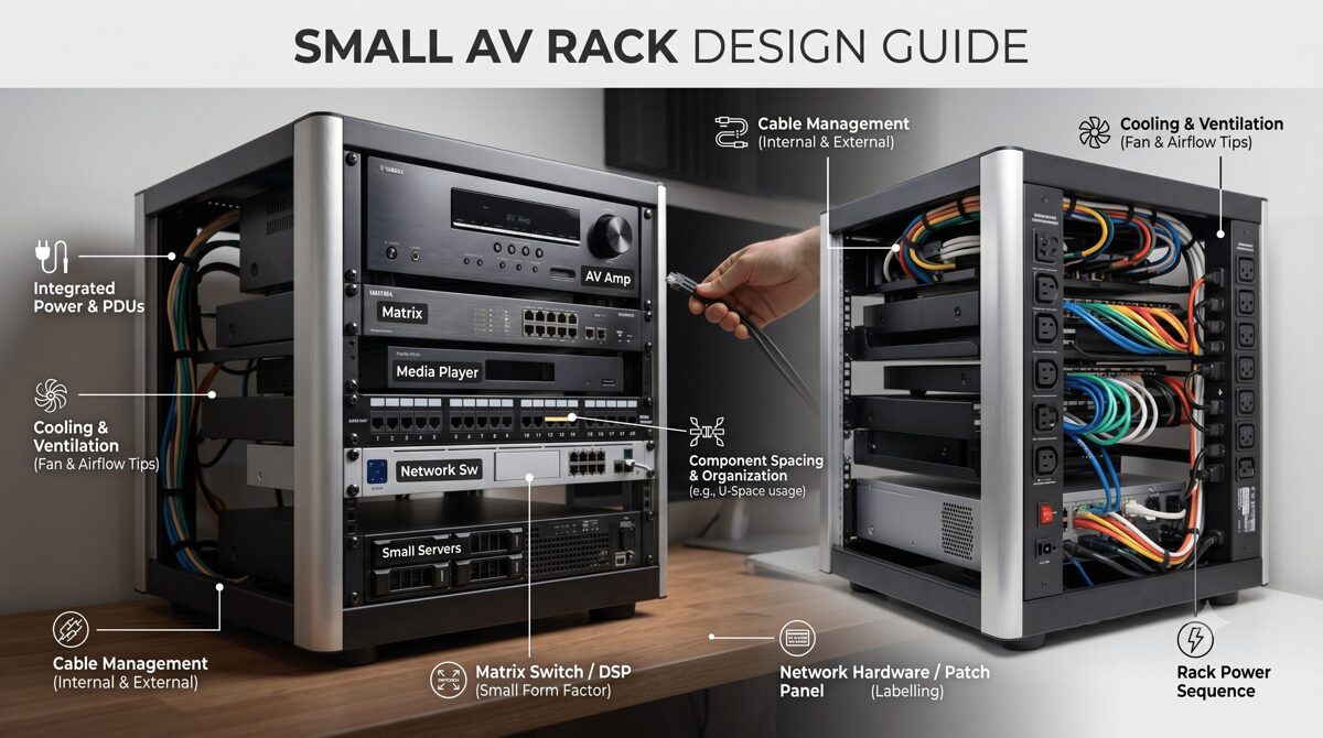
Best Practice 2: Comprehensive Documentation Standards
Documentation Philosophy: “If it’s not documented, it doesn’t exist.”
Network Architecture Documentation:
High-Level Design Documents:
Contents:
1. Executive Summary
– Project scope and objectives
– Architecture overview
– Key design decisions and rationale
2. Physical Topology
– Building connectivity diagram
– Equipment rack locations
– Cable pathway maps
– Power distribution
3. Logical Architecture
– VLAN design and numbering
– IP addressing scheme
– Routing design (protocols, areas, summarization)
– Multicast architecture (PIM, RP placement)
4. Security Architecture
– Trust zones and boundaries
– Firewall rules and ACLs
– Authentication and authorization
– Monitoring and logging
5. QoS Design
– Classification strategy
– Marking and queuing policies
– Bandwidth allocations
– End-to-end implementation
6. Redundancy and Resilience
– Failure scenarios and recovery
– Backup power (UPS, generator)
– Disaster recovery procedures
Detailed Implementation Documentation:
IP Address Management (IPAM):
Comprehensive Spreadsheet or Database:
Columns:
– VLAN ID and Name
– IP Subnet (network/mask)
– Gateway IP
– DHCP Range
– Reserved IPs (static assignments)
– Device Name
– Device Type
– MAC Address
– Switch/Port Location
– Primary User/Purpose
– Installation Date
– Last Verified Date
– Notes
Updates:
– Real-time updates during deployment
– Quarterly verification audits
– Reconciliation with network discovery tools
Port Assignment Database:
For Each Switch Port:
– Switch hostname and model
– Port number (Gi1/0/12)
– Port description
– Connected device (hostname and type)
– VLAN assignment
– PoE enabled/disabled and power draw
– Port speed/duplex
– Cable ID and destination
– Installation date
– Last verified date
– Port configuration (access/trunk)
As-Built Drawings:
-
Floor plans: Equipment locations, cable runs marked
-
Rack elevations: All equipment positioned and labeled
-
Logical diagrams: VLANs, routing, traffic flows
-
Cable schedules: Complete listing of all connections
Configuration Backups:
Automated Daily Backups:
1. Collection:
– Automated scripts pulling configs from all devices
– Scheduled during low-usage periods (2-4 AM)
– TFTP, SCP, or API-based retrieval
2. Version Control:
– Git repository for all configurations
– Commit messages describing changes
– Change attribution (who made change)
– Ability to diff and rollback
3. Secure Storage:
– Encrypted storage (configs contain sensitive info)
– Offsite replication for disaster recovery
– Access controls (who can view/restore)
4. Compliance:
– Retention policies (7 years typical)
– Audit trail for regulatory requirements
Operational Documentation:
Standard Operating Procedures (SOPs):
-
Device onboarding: Adding new AV endpoint to network
-
VLAN provisioning: Creating and propagating new VLANs
-
Firmware updates: Testing and deployment process
-
Incident response: Troubleshooting workflows
-
Change management: Approval and implementation procedures
Runbooks:
Troubleshooting Runbook Example:
Symptom: Video Conference Quality Issues
Step 1: Identify Scope
– Single room or multiple?
– Single site or multiple?
– Started when? (correlate to changes)
– Consistent or intermittent?
Step 2: Check Network Path
– Verify endpoint online (ping)
– Check switch port (errors, utilization)
– Verify VLAN assignment
– Check trunk links (saturation?)
– Review QoS stats
Step 3: Check AV Device
– Firmware version current?
– Bandwidth consumption vs expected?
– Packet loss/jitter measurements?
– Recent configuration changes?
Step 4: End-to-End Testing
– Test call to known-good endpoint
– Packet capture during issue
– Check multicast if applicable
Step 5: Escalation
– To vendor support if device issue
– To network team if infrastructure problem
– To management if critical business impact
Training Materials:
-
End-user guides: How to use collaboration rooms
-
Support staff training: Troubleshooting common issues
-
Administrator training: Advanced configuration and management
Documentation Tools:
Recommended Platforms:
-
Confluence/SharePoint: Centralized wiki for all documentation
-
NetBox: Open-source IPAM and network documentation
-
Visio/Draw.io: Network diagrams
-
Git/GitLab: Configuration version control
-
Solarwinds NPM: Automated network discovery and documentation
Best Practice 3: Automated Provisioning and Configuration
Zero-Touch Deployment:
Provisioning Workflow:
1. Device Acquisition:
– New switch delivered to site
– Racked and powered on
– Connected to network
2. Automated Discovery:
– Switch obtains IP via DHCP
– DHCP option 150 points to configuration server
– Switch downloads initial config via TFTP/HTTP
3. Configuration Application:
– Base config applied (hostname, management, VLANs)
– Device-specific settings (IP, location)
– Verification tests run automatically
4. Registration:
– Device added to monitoring systems
– Inventory database updated
– Certificates provisioned for secure management
5. Production Ready:
– Total time: 10-15 minutes from power-on
– No manual configuration required
– Consistent with all other switches
Configuration Management with Ansible:
Example Playbook Structure:
yaml
# Enterprise AV Switch Deployment Playbook
– name: Deploy Standard Enterprise AV Switch Configuration
hosts: access_switches
gather_facts: no
tasks:
– name: Set hostname
ios_config:
lines:
– hostname {{ inventory_hostname }}
– name: Configure VLANs
ios_vlan:
vlan_id: “{{ item.id }}”
name: “{{ item.name }}”
loop: “{{ vlans }}”
– name: Configure trunk ports
ios_interface:
name: “{{ item.name }}”
mode: trunk
trunk_allowed_vlans: “{{ trunk_vlans }}”
trunk_native_vlan: 999
loop: “{{ trunk_ports }}”
– name: Configure access ports for AV endpoints
ios_interface:
name: “{{ item.name }}”
mode: access
access_vlan: “{{ item.vlan }}”
description: “{{ item.description }}”
loop: “{{ access_ports }}”
– name: Configure QoS policies
ios_config:
src: templates/qos_policy.j2
– name: Save configuration
ios_command:
commands:
– write memory
Benefits of Automation:
-
Deployment speed: 100 switches configured in 1 hour vs 1 week manual
-
Error reduction: Eliminate typos and misconfigurations
-
Consistency: Identical configuration across all devices
-
Auditability: All changes tracked in version control
-
Rollback: Restore previous configuration in minutes
-
Testing: Validate configurations before production deployment
Best Practice 4: Proactive Monitoring and Analytics
Multi-Layer Monitoring Strategy:
Infrastructure Monitoring:
Network Equipment Health:
Monitored Metrics:
Switches:
– CPU utilization (alert >70%, critical >90%)
– Memory utilization (alert >80%, critical >95%)
– Temperature (alert >60°C, critical >70°C)
– Fan status (alert on failure)
– Power supply status (alert on failure)
– Uptime (track for stability)
Interfaces:
– Port status (up/down alerts)
– Bandwidth utilization (alert >70%, critical >85%)
– Error rates (CRC, collisions, drops)
– Packet loss percentage
– Latency and jitter
– PoE consumption and budget remaining
VLANs:
– Bandwidth consumption per VLAN
– Device count per VLAN
– Multicast group count
Trunks:
– Utilization trends (capacity planning)
– Error rates
– Native VLAN mismatches
– VLAN allowed list consistency
AV Device Monitoring:
Endpoint Health Tracking:
Per-Device Metrics:
Encoders/Decoders:
– Online/offline status
– Active streams (count and bitrate)
– Packet loss and jitter
– Firmware version compliance
– CPU/memory/temperature
– Configuration drift detection
Video Conferencing Systems:
– Call statistics (duration, participants)
– Audio/video quality metrics (MOS scores)
– Bandwidth consumption
– Failed call attempts
– Peripheral status (camera, mic, speaker)
– Firmware version
Control Processors:
– Online/offline status
– Control responsiveness (latency)
– Program execution errors
– Memory leaks detection
– Network connectivity
Audio DSPs:
– Dante channel status
– Latency and clock offset
– Input/output levels
– Feedback detection
– PTP synchronization
Application Performance Monitoring (APM):
Synthetic Testing:
Automated Test Scenarios:
Video Conference Test:
– Scheduled every hour
– Bot initiates call between two test rooms
– Measures:
– Call setup time
– Audio quality (MOS score)
– Video quality (resolution, frame rate)
– Packet loss and jitter
– Call stability (drops?)
– Alert if any metric below threshold
Wireless Presentation Test:
– Every 2 hours
– Automated device connects and shares content
– Measures:
– Discovery time
– Connection establishment time
– Streaming quality
– Latency
– Alert on failures
AV-over-IP Stream Test:
– Continuous multicast stream from encoder to decoder
– Measures every 60 seconds:
– Stream availability
– Bitrate consistency
– Packet loss
– Jitter
– Alert if any impairment detected
User Experience Monitoring:
Real User Measurements:
-
NPS surveys: After each meeting, rate experience (1-10)
-
Usage analytics: Meetings per room, average duration
-
Support tickets: Correlation with network events
-
Call quality data: From UCaaS platforms (Zoom, Teams metrics)
AI-Powered Analytics:
Machine Learning Applications:
Anomaly Detection:
Baseline Learning:
1. Normal Behavior Profile:
– Bandwidth patterns by time of day/week
– Typical error rates
– Standard device behaviors
– Usage patterns (busiest meeting times)
2. Real-Time Analysis:
– Compare current metrics to learned baseline
– Flag deviations exceeding thresholds
– Example: Switch CPU spiking to 80% at 2 AM
(normally <10% = potential security incident)
3. Intelligent Alerting:
– Reduce false positives by 90%
– Focus on truly unusual events
– Context-aware alerts (critical meeting in progress?)
Predictive Failure Analysis:
Predictive Maintenance:
1. Collect Historical Data:
– Device failures and preceding symptoms
– Gradual degradation patterns
– Environmental factors (temperature trends)
2. Train ML Models:
– Identify failure indicators
– Calculate probability of failure
– Predict time-to-failure
3. Proactive Replacement:
– Alert when failure likely within 30 days
– Schedule preventive maintenance
– Replace before user impact
Example:
– Switch fan noise increasing (vibration sensor)
– Temperature trending upward over 3 months
– ML model: 85% probability of failure in 14 days
– Action: Schedule replacement during maintenance window
Capacity Forecasting:
Trend Analysis:
1. Historical Growth Tracking:
– Bandwidth utilization month-over-month
– Port consumption rate
– PoE budget utilization
– IP address allocation
2. Forecasting Models:
– Linear, exponential, or seasonal models
– Predict resource exhaustion dates
– Account for planned expansions
3. Proactive Capacity Management:
– 6-month forecast triggers planning
– 3-month forecast triggers procurement
– Avoid capacity-related outages
Example Output:
“Building 3 trunk links will reach 85% utilization
in 4 months based on current 8%/month growth rate.
Recommend upgrade from 10G to 40G by Q3.”
Monitoring Tools Ecosystem:
Recommended Platforms:
Network Monitoring:
-
SolarWinds Network Performance Monitor: Comprehensive infrastructure monitoring
-
PRTG: Mid-market alternative with flexible sensors
-
Cisco DNA Center Assurance: Integrated with Cisco infrastructure
-
Grafana + Prometheus: Open-source time-series monitoring
AV Management:
-
Crestron Fusion: Crestron ecosystem monitoring and control
-
Extron GlobalViewer Enterprise: Multi-vendor AV device monitoring
-
Q-SYS Reflect: Q-SYS cloud-based management
-
Domotz: Cloud-based monitoring for distributed networks
Analytics and AI:
-
Martello Vantage DX: AI-driven UC platform monitoring
-
ThousandEyes: End-to-end visibility including Internet paths
-
Splunk: Log aggregation and analysis with ML capabilities
Best Practice 5: Change Management and Testing
Formal Change Management Process:
Change Types:
Emergency Change (Immediate):
– Critical outage requiring immediate fix
– Security vulnerability requiring urgent patch
– Approval: On-call manager
– Documentation: Post-implementation
Standard Change (Pre-approved):
– Routine activities (adding port to VLAN)
– Pre-tested procedures with low risk
– Approval: Automated or standing approval
– Documentation: Lightweight
Normal Change (Planned):
– VLAN additions, routing changes
– Firmware updates
– Major configuration modifications
– Approval: Change Advisory Board
– Documentation: Comprehensive
Major Change (High Risk):
– Core network upgrades
– WAN circuit migrations
– Data center relocations
– Approval: Executive leadership
– Documentation: Extensive, with rollback plans
Change Management Workflow:
Request for Change (RFC) Submission:
1. Change Request Form:
– Summary and detailed description
– Business justification
– Risk assessment (low/medium/high)
– Impact analysis (scope of affected systems)
– Implementation plan (step-by-step)
– Testing plan
– Rollback plan
– Required resources (people, tools)
– Estimated duration
– Maintenance window request
2. Review and Approval:
– Technical review by peers
– Risk assessment by security team
– Business impact review
– Change Advisory Board meeting
– Approval or request modifications
3. Implementation:
– Scheduled during approved maintenance window
– Communication to stakeholders (3-7 days notice)
– Pre-change testing in lab
– Change implementation following plan
– Verification testing
– Post-change monitoring (24-48 hours)
4. Documentation:
– Update network documentation
– Close change ticket
– Lessons learned (if issues occurred)
Testing Methodology:
Lab Environment:
Pre-Production Testing:
Lab Setup:
– Replicate production topology at small scale
– Same switch models and firmware versions
– Representative AV devices
– Traffic generators simulating load
Test Scenarios:
1. Functional Testing:
– Does change achieve desired outcome?
– All features work as expected?
2. Performance Testing:
– Bandwidth throughput adequate?
– Latency within acceptable limits?
– QoS functioning correctly?
3. Failure Testing:
– Failover mechanisms work?
– Recovery time acceptable?
– No unexpected side effects?
4. Compatibility Testing:
– All AV devices still function?
– No conflicts with existing configs?
5. Rollback Testing:
– Can change be reversed?
– Rollback procedure works reliably?
Production Testing:
Staged Rollout:
Phase 1: Pilot (1-5% of sites)
– Deploy to least critical buildings first
– Monitor for 1-2 weeks
– Collect feedback and metrics
– Adjust as needed
Phase 2: Limited Production (5-25%)
– Expand to additional sites
– Include mix of critical and non-critical
– Monitor for 2-4 weeks
– Validate at scale
Phase 3: Broad Deployment (25-100%)
– Accelerate rollout if no issues
– Complete remaining sites
– Ongoing monitoring
Benefits:
– Issues discovered with minimal impact
– Time to refine procedures
– Build confidence before critical deployments
Essential Components of a Large Enterprise AV Network
Network Switches and Infrastructure
Enterprise Switch Selection Criteria:
Access Layer Switches:
Required Features:
-
PoE++ (802.3bt): 60-100W per port for high-power AV devices
-
Port density: 24 or 48 ports optimal (balance capacity vs management)
-
Uplinks: Dual 10 Gbps SFP+ for redundancy and bandwidth
-
Stacking: Support for virtual chassis (simplifies management)
-
Layer 2/3: Both capabilities for flexibility
-
IGMP snooping v3: Multicast optimization
-
QoS: 802.1p/DSCP marking, multiple queues (4+ queues minimum)
-
VLANs: 4,096 VLAN support
-
PoE budget: Minimum 740W for 24-port, 1440W for 48-port
-
Management: CLI (SSH), web interface, SNMP v3, RESTful API
Recommended Models (2026):
-
Cisco Catalyst 9300-24U/48U: Full PoE++, 10G uplinks, stackable
-
Aruba CX 6300M: Intuitive management, full Layer 3, stackable
-
Juniper EX4400: High PoE capacity, low latency
-
Dell PowerSwitch N3248TE-ON: Cost-effective with full features
Distribution Layer Switches:
Required Features:
-
Port capacity: 48+ ports for uplinks from access layer
-
Uplink capacity: 40 Gbps or 100 Gbps to core
-
Switching fabric: 1-2 Tbps non-blocking
-
Layer 3 routing: Full-featured (OSPF, EIGRP, BGP)
-
Redundancy: Chassis with redundant supervisors or VSS/VPC
-
PIM sparse mode: Multicast routing
-
QoS: Robust queuing and shaping
-
Services: DHCP relay, first-hop redundancy (HSRP/VRRP)
Recommended Models:
-
Cisco Catalyst 9500: Modular, highly scalable, full feature set
-
Aruba CX 8325: 100G capable, modern OS
-
Juniper EX4650: High-density 10G with 40/100G uplinks
Core Layer Switches:
Required Features:
-
Switching capacity: 5-25 Tbps
-
Port speeds: 40/100/400 Gbps
-
Latency: <1 microsecond
-
Redundancy: Full hardware redundancy (supervisors, fabrics, power)
-
Scalability: Modular to grow with needs
-
Protocols: BGP for WAN, OSPF for campus
Recommended Models:
-
Cisco Catalyst 9600: Modular, scales to 25 Tbps
-
Aruba CX 8400: Chassis-based, cloud-managed option
-
Juniper QFX10000: Ultra-low latency, data center optimized
PoE Power Budget Planning:
Calculating Total PoE Requirements:
Example Medium Conference Room:
Device Power Draw:
– PTZ Camera: 25W (PoE+)
– Ceiling Mic Array: 18W (PoE+)
– Control Touch Panel: 15W (PoE+)
– Wireless Gateway: 12W (PoE)
– Room Scheduling Display: 8W (PoE)
Total per Room: 78W
Building with 50 Rooms:
50 rooms × 78W = 3,900W total
Add 20% safety margin: 4,680W required
Switch Selection:
48-port PoE++ switches with 1440W budget:
4,680W ÷ 1440W = 3.25 switches minimum
Deploy: 4 switches for capacity and redundancy
Structured Cabling Infrastructure
Copper Cabling Standards:
Cat6a – Recommended Minimum:
-
Bandwidth: 500 MHz
-
Speed: 10GBASE-T to 100 meters
-
PoE: Supports PoE++ without temperature concerns
-
Cost: Moderate (15-20% more than Cat6)
-
Future-proofing: Good for 10-15 year lifespan
-
Use case: Standard for all enterprise AV deployments
Cat7/Cat7a – Premium Option:
-
Bandwidth: 600-1,000 MHz
-
Shielding: F/FTP (fully shielded)
-
EMI resistance: Excellent for electrically noisy environments
-
Speed: 10GBASE-T to 100m, potentially 40GBASE-T
-
Cost: Premium (40-50% more than Cat6a)
-
Use case: Medical facilities, industrial, high-EMI areas
Cat8 – Future Technology:
-
Bandwidth: 2,000 MHz
-
Speed: 25GBASE-T and 40GBASE-T to 30 meters
-
Use case: Data center, extremely high-bandwidth point-to-point
-
Cost: Very high (2-3× Cat6a)
-
Use case for AV: Limited to special circumstances
Fiber Optic Cabling:
Single-Mode Fiber (SMF):
-
Use case: Building-to-building, campus backbone, long distances (>1km)
-
Distance: Up to 10-40km depending on optics
-
Speeds: 10G, 40G, 100G, 400G
-
Cost: Higher transceiver cost, lower cable cost
-
Future-proof: Bandwidth upgrades via transceiver changes only
Multimode Fiber (MMF):
OM3:
-
Distance: 10 Gbps to 300m, 40 Gbps to 100m
-
Core size: 50 μm
-
Cost: Moderate
-
Use case: Floor-to-floor, intra-building distribution
OM4:
-
Distance: 10 Gbps to 550m, 40 Gbps to 150m, 100 Gbps to 100m
-
Core size: 50 μm
-
Cost: Slightly higher than OM3
-
Use case: Current standard for most enterprise intra-building
OM5 (Wideband Multimode):
-
Features: Supports multiple wavelengths (WDM) for higher capacity
-
Distance: Similar to OM4
-
Use case: Future technology, emerging adoption
Cabling Best Practices:
Installation Standards:
TIA/EIA-568-C Compliance:
Copper Termination:
– T568A or T568B consistently (T568B more common)
– Minimize untwisting (1/2 inch maximum)
– Proper jacket strip (no more than 1 inch exposed)
– Cable bend radius: Minimum 4× cable diameter
– No kinks, sharp bends, or excessive tension
– Cable ties not over-tightened (causes crushing)
Fiber Termination:
– Fusion splicing for permanent connections (lowest loss)
– Factory-terminated jumpers (pre-tested, reliable)
– Proper connector cleaning (lint-free wipes, alcohol)
– Polarity verification (LC, SC, MPO connectors)
Testing and Certification:
– All permanent links tested with Fluke DSX or equivalent
– Test to deployed category (Cat6a test for Cat6a cable)
– Document all test results (pass/fail with margins)
– Failed cables remediated before acceptance
Cable Management:
Organization Standards:
Pathways:
– Dedicated cable trays for horizontal runs
– Vertical risers properly fire-rated
– Separation from electrical (12-inch minimum)
– Support every 4-5 feet (prevents sagging)
Labeling:
– Both ends of every cable labeled
– Labels include:
– Building-Floor-IDF-Port number
– Destination device or room
– Cable type (Cat6a, OM4, etc.)
– Installation date
– Test status (pass/fail)
– Machine-printed labels (Brady, Brother)
– Laminated or heat-shrink for durability
Color Coding:
– Blue: Horizontal (access layer)
– Yellow: Backbone (distribution/core)
– Red: Critical systems (security, life safety)
– Green: BYOD/guest networks
– White: Reserved/future use
Documentation:
– Cable database with all connections
– As-built drawings showing actual routes
– Test reports for every cable
– Photos of rack layouts and connections
AV Endpoints and Edge Devices
Video Distribution Endpoints:
Encoders:
-
Input interfaces: HDMI, DisplayPort, SDI, DVI, VGA
-
Encoding technologies: H.264, H.265, JPEG2000, uncompressed (SDVoE)
-
Bandwidth: 10 Mbps (H.265) to 10 Gbps (uncompressed 4K)
-
Latency: <1ms (uncompressed) to 100ms (highly compressed)
-
Power: PoE+ or PoE++ depending on model
-
Management: Web interface, API, centralized platform
Decoders:
-
Output interfaces: HDMI, DisplayPort, SDI
-
Scaling: Built-in scaler for resolution matching
-
De-interlacing: For interlaced sources
-
Audio: De-embedding and volume control
-
Video wall: Bezel compensation, rotation, cropping
Unified Communications Endpoints:
Zoom Rooms:
-
Compute: Zoom Rooms appliance or PC
-
Displays: Primary display + content display
-
Camera: USB PTZ or built-in camera
-
Audio: USB soundbar or separate mic/speaker
-
Control: Zoom Rooms Controller (touch panel)
-
Network: 1 Gbps Ethernet recommended
Microsoft Teams Rooms:
-
Compute: Certified MTR appliance
-
Displays: Single or dual displays
-
Camera: USB camera (variety of options)
-
Audio: Certified audio devices (Jabra, Poly, Shure, Biamp)
-
Control: Touch console
-
Peripherals: Content camera, whiteboards
Cisco Webex Rooms:
-
Form factors: Desk (personal), Room Kit (small), Room 55/70 (medium/large)
-
Integrated: Camera, microphones, speakers, codec
-
Displays: External (Room Kit) or integrated (Room 55/70)
-
Management: Webex Control Hub (cloud)
Audio-over-IP Infrastructure:
Dante Networking:
-
Latency: 150 microseconds (typical)
-
Sample rates: 44.1-192 kHz
-
Bit depth: 16, 24, or 32-bit
-
Channels: Up to 512×512 at 48kHz
-
Redundancy: Primary and secondary network paths
-
PTP: Precision Time Protocol for synchronization
-
VLAN: Dedicated VLAN recommended for Dante
Endpoints:
-
DSP processors: Biamp Tesira, QSC Q-SYS, Yamaha MTX/MRX
-
Microphones: Shure MXA, Sennheiser TeamConnect, Audio-Technica
-
Speakers: JBL Control, QSC, Yamaha
-
Amplifiers: Crown, QSC, Powersoft
-
Interfaces: Audio I/O for legacy equipment integration
Wireless Presentation:
Technologies:
-
Barco ClickShare: Proprietary button or app-based
-
Mersive Solstice: Software-based, BYOD-friendly
-
Crestron AirMedia: Integrated with Crestron ecosystem
-
Kramer VIA: Enterprise wireless collaboration
Features:
-
Multi-user: 4-8 simultaneous sources
-
Moderation: Host controls who presents
-
BYOD support: Windows, Mac, iOS, Android, Chromebook
-
Protocols: Miracast, AirPlay, Chromecast, proprietary
-
Security: WPA2-Enterprise, VLAN isolation
-
Network: Dedicated VLAN for guest access
Digital Signage:
Players:
-
BrightSign: Robust, purpose-built signage players
-
Samsung: Smart signage displays with built-in players
-
Chrome OS: Affordable, cloud-managed
-
Raspberry Pi: Ultra-low-cost for simple signage
Content Management Systems (CMS):
-
Scala: Enterprise-grade with advanced features
-
Four Winds Interactive: Cloud-based, intuitive
-
Signagelive: Flexible, supports multiple player types
-
Carousel: Digital signage and space management
Deployment Considerations:
-
Content distribution: Centralized server or cloud-based
-
Bandwidth: Pre-cache content locally vs stream
-
Scheduling: Time-based, triggered by events
-
Interactivity: Touch-enabled displays for wayfinding
How AV-over-IP Technologies Impact Enterprise Network Design
AV-over-IP Technology Comparison
Uncompressed vs Compressed:
|
Technology
|
Bandwidth
|
Latency
|
Quality
|
Network Req
|
Use Case
|
|
SDVoE
|
10 Gbps
|
<1ms
|
Lossless
|
10G dedicated
|
Surgical, production, mission-critical
|
|
Dante AV
|
150-500 Mbps
|
16-33ms
|
Very high
|
1G shared
|
Corporate, education, worship
|
|
NDI
|
10-150 Mbps
|
60-120ms
|
High
|
1G shared
|
Broadcast, production, content creation
|
|
JPEG2000
|
100-300 Mbps
|
1-5ms
|
Very high
|
1G shared
|
General enterprise
|
|
H.264/H.265
|
4-50 Mbps
|
50-150ms
|
Good-high
|
1G shared
|
Low-bandwidth, cloud
|
Network Design Implications
Bandwidth Planning for AV-over-IP:
SDVoE Deployments:
Requirements:
– Dedicated 10 Gbps switch fabric
– Low latency switches (<10 microseconds)
– No oversubscription (non-blocking architecture)
– Minimal hops between source and destination
Cost Implications:
– 10G switches: 2-3× cost of 1G switches
– Fiber upgrades may be required
– Higher power consumption
– Specialized expertise needed
When to Use:
– Zero latency required (surgical displays)
– Pristine image quality mandatory (radiology)
– Live production switching (broadcast, events)
– Mission-critical operations centers
Compressed AV-over-IP Deployments:
Requirements:
– Standard 1 Gbps network adequate
– QoS for traffic prioritization
– IGMP snooping for multicast
– Moderate latency tolerance (16-100ms)
Cost Implications:
– Standard enterprise switches sufficient
– Existing infrastructure often adequate
– Lower CapEx and OpEx
– Easier to scale
When to Use:
– 95% of enterprise conference rooms
– Digital signage networks
– Distributed collaboration
– General AV distribution
VLAN Strategy for Large-Scale AV-over-IP:
Functional Segmentation:
Enterprise VLAN Design:
Video Distribution:
– VLAN 100-199: Video encoders/decoders
– Subdivided by technology if needed:
– VLAN 100-109: SDVoE (if deployed)
– VLAN 110-119: Dante AV
– VLAN 120-129: NDI
– VLAN 130-139: Other compressed
Audio-over-IP:
– VLAN 200-299: Dante, AES67, AVB
– Dedicated for timing-critical audio
– PTP configured for synchronization
Control Systems:
– VLAN 300-399: Control processors, touch panels
– Separate from media streams
– Lower QoS priority than media
Conferencing:
– VLAN 400-499: Video conferencing codecs/room systems
– Isolation from general AV (different security posture)
– Direct Internet access for cloud services
Wireless Presentation:
– VLAN 500-599: BYOD wireless collaboration
– Guest/semi-trusted VLAN
– Isolated from corporate network
Management:
– VLAN 900-999: AV management and monitoring
– Admin access only
– Jump box for secure administration
Multicast Optimization:
Large-Scale Multicast Design:
Enterprise Multicast Architecture:
1. IGMP Snooping Per VLAN:
– Enabled on all AV VLANs
– IGMP querier on distribution layer SVI
– Fast-leave for rapid group departures
– IGMP v3 for SSM support
2. PIM Sparse Mode:
– Rendezvous Points on distribution layer
– Anycast RP for redundancy
– Multiple RPs for load distribution
– Careful RP placement for optimal paths
3. Multicast Boundaries:
– Prevent AV multicast from leaking to WAN
– Admin-scoped addressing (239.0.0.0/8)
– ACLs on VLAN boundaries
4. Monitoring:
– Track multicast group count per switch
– Alert when approaching table capacity (70%)
– Monitor RP load and redistribute if needed
– Packet captures for troubleshooting
Source-Specific Multicast (SSM):
Benefits for Enterprise:
Traditional Multicast (*,G):
– Receiver joins group (*,239.1.1.1)
– Any source can send to group
– Requires Rendezvous Point
– More complex, more state
SSM (S,G):
– Receiver specifies source (10.100.1.5,239.1.1.1)
– Only designated source allowed
– No RP required (source-based trees immediately)
– Better security (prevents rogue sources)
– Less network state
Implementation:
– IGMPv3 required (supports (S,G) joins)
– Address range: 232.0.0.0/8 reserved for SSM
– Configure on Dante AV and other modern protocols
– Simplifies large multicast deployments
Bandwidth Aggregation Strategies
Aggregate Bandwidth Calculation:
Example Large Enterprise:
Organization:
– 50 buildings across campus
– 1,000 conference rooms total
– 30% simultaneous usage during peak
Per-Room Bandwidth (average):
– Video conferencing: 20 Mbps
– Wireless presentation: 15 Mbps
– AV-over-IP (if applicable): 50 Mbps
– Control/management: 2 Mbps
Total per active room: 87 Mbps
Peak Aggregate:
1,000 rooms × 30% × 87 Mbps = 26.1 Gbps
Design Recommendations:
– Access to Distribution: 10 Gbps uplinks
– Distribution to Core: 40 Gbps uplinks
– Core backbone: 100 Gbps
– Internet: 10-20 Gbps (for cloud conferencing)
Growth Buffer:
– Design for 50-100% growth: 40-50 Gbps core minimum
– Plan technology refresh cycle: 5-7 years
– Modular approach: Add capacity incrementally
Future Trends in Enterprise AV Networking
Trend 1: AI-Native Network Operations
AIOps for AV Networks:
Current State (2026): Major adoption of AI-powered network operations in enterprise:
Capabilities:
-
Anomaly detection: 95% accurate identification of unusual behavior
-
Predictive failure: 60-90 day advance warning of hardware failures
-
Root cause analysis: Automated troubleshooting reducing MTTR by 60%
-
Capacity forecasting: Trend-based predictions for infrastructure planning
-
Self-healing: Automated remediation of common issues without human intervention
Implementation:
AI-Powered Monitoring Stack:
Data Collection:
– SNMP polling: Device metrics every 1-5 minutes
– NetFlow/sFlow: Granular traffic analysis
– Syslog: Event and error messages
– API polling: AV device status and performance
– Synthetic testing: Continuous end-to-end validation
ML Model Training:
– Baseline learning: 30-90 days of normal behavior
– Supervised learning: Known failure patterns
– Unsupervised learning: Detect unknown anomalies
– Continuous retraining: Adapt to changing patterns
Automated Response:
– Low severity: Log for review, no immediate action
– Medium severity: Alert on-call engineer, provide diagnostic data
– High severity: Automatic remediation (restart service, failover)
– Critical: Immediate escalation, automated recovery if possible
Human-in-the-Loop:
– AI suggests actions, human approves
– Builds trust and prevents unexpected impacts
– Gradually increase automation as confidence grows
Vendors Leading AIOps:
-
Cisco DNA Center: Intent-based networking with AI assurance
-
Mist AI (Juniper): Marvis virtual assistant for troubleshooting
-
Aruba NetInsight: Predictive AI for Aruba networks
-
IBM Watson AIOps: Multi-vendor platform with advanced AI
Trend 2: Cloud-Native and Hybrid Architectures
Shift to Cloud Services:
Cloud-First AV Services:
-
Video conferencing: 95% cloud-based (Zoom, Teams, Webex)
-
Content management: Cloud CMS for digital signage
-
Device management: Cloud platforms for AV endpoints
-
Recording and streaming: Cloud storage and transcoding
-
Analytics: Cloud-based usage and performance analytics
Hybrid Architecture Patterns:
Enterprise Hybrid Model:
Cloud Services:
– Video conferencing control plane
– Content management and scheduling
– Device management and monitoring
– Analytics and reporting
– Recording storage
On-Premises:
– Media processing (low-latency requirements)
– High-bandwidth AV distribution (multicast)
– Sensitive content (compliance requirements)
– Local failover for business continuity
Network Implications:
– Direct Internet access from meeting rooms
– SD-WAN optimizing cloud application performance
– Local caching for frequently accessed content
– Adequate Internet bandwidth (10-100 Gbps)
Multi-Cloud Strategies:
Redundancy Across Providers:
Primary: Microsoft Teams (on Microsoft Azure)
Backup: Zoom (on AWS and Oracle Cloud)
Benefits:
– Provider outage doesn’t affect all services
– Vendor negotiation leverage
– Best-of-breed for different use cases
– Compliance (data residency) flexibility
Network Design:
– Multiple Internet providers (diverse paths)
– SD-WAN routing to optimal cloud provider
– Local Internet breakout at each site
– QoS for cloud traffic on WAN links
Trend 3: Intent-Based Networking
Declare Outcomes, Not Configurations:
Traditional Approach: “Configure VLAN 100 on ports Gi1/0/12-24 on switches 1-50…”
Intent-Based Approach: “All conference rooms in Building 1 need video distribution with high QoS priority”
System Automatically:
-
Identifies conference rooms and associated ports
-
Creates appropriate VLANs if don’t exist
-
Configures ports with correct settings
-
Applies QoS policies
-
Verifies implementation successful
-
Continuously ensures intent maintained
Benefits for Enterprise AV:
-
Faster deployments: New building configured in hours vs weeks
-
Consistency: Human errors eliminated
-
Self-healing: System automatically corrects drift
-
Simplicity: Business language vs technical commands
-
Audit compliance: Continuous verification of policies
Implementation Platforms:
-
Cisco DNA Center: Mature IBN platform
-
Apstra (Juniper): Data center focused, expanding to enterprise
-
Aruba NetConductor: Intent-based campus networking
Trend 4: 5G and WiFi 7 Integration
Wireless First Networks:
5G Private Networks: Enterprises deploying private 5G for:
-
Ultra-reliable low latency (1ms latency, 99.999% reliability)
-
Massive IoT connectivity (1M devices/km²)
-
Mobility: Seamless handoff across campus
-
Network slicing: Dedicated slice for AV traffic
Use Cases for AV:
-
Wireless AV-over-IP: Replace cables with 5G
-
Mobile collaboration: Truly wireless meeting rooms
-
Outdoor venues: Concerts, stadiums, events
-
Temporary installations: Trade shows, conferences
-
Vehicle connectivity: Mobile broadcast units
WiFi 7 (802.11be): Key Features:
-
Bandwidth: Up to 30 Gbps theoretical
-
Latency: <5ms typical
-
Capacity: 4× improvement over WiFi 6
-
Multi-Link Operation: Simultaneous transmission on multiple bands
AV Applications:
-
Wireless video conferencing: Reliable 4K wireless
-
Wireless presentation: Zero-latency screen sharing
-
Mobile devices: Seamless roaming across campus
-
IoT sensors: Building automation integration
Network Integration:
Unified Wired/Wireless Architecture:
VLAN Mapping:
– Wired VLAN 100 (AV-VIDEO) → WiFi SSID “Enterprise-AV”
– Seamless mobility between wired and wireless
– Same IP subnet, no re-authentication
– Consistent QoS policies
5G Network Slicing:
– Slice 1: Corporate AV (high priority, guaranteed bandwidth)
– Slice 2: Guest wireless (best effort)
– Slice 3: IoT sensors (massive connectivity, low bandwidth)
Handoff Optimization:
– Fast roaming (<50ms handoff time)
– Predictive handoff before signal degrades
– Load balancing across APs/cells
Trend 5: Sustainable and Green IT
Energy-Efficient AV Networks:
Power Consumption Focus:
Enterprise Power Consumption:
Network Equipment:
– 500 access switches × 300W = 150 kW
– 50 distribution switches × 500W = 25 kW
– 10 core switches × 2,000W = 20 kW
– Total network: 195 kW continuous
At $0.15/kWh:
– Annual cost: $256,000
– 5-year cost: $1.28M
10% Efficiency Improvement:
– Annual savings: $25,600
– 5-year savings: $128,000
– Plus environmental benefit
Efficiency Strategies:
Energy-Efficient Hardware:
-
Next-gen switches: 30-40% more efficient than 5-year-old equipment
-
PoE efficiency: 802.3bt Class 8 (90% efficiency vs 70% older PoE)
-
Proper sizing: Right-size switch capacity (oversized wastes power)
Intelligent Power Management:
Automated Power Savings:
Schedule-Based:
– Shut down displays after hours (50% of endpoints)
– Reduce PoE to idle devices (EEE – Energy Efficient Ethernet)
– Power down unused switch ports
Occupancy-Based:
– IoT sensors detect room vacancy
– Power down AV equipment automatically
– Wake-on-LAN when room occupied
Estimated Savings:
– 30-50% reduction in AV equipment power
– $75,000-125,000 annually for large enterprise
– ROI: 12-18 months on automation investment
Renewable Energy:
-
On-site solar: Offset network power consumption
-
PPA agreements: Purchase renewable energy
-
Carbon offsets: Neutralize remaining emissions
Lifecycle Management:
-
E-waste recycling: Responsible disposal of old equipment
-
Equipment reuse: Redeploy functional equipment to less critical areas
-
Circular economy: Buy-back and refurbishment programs
Trend 6: Zero-Trust Security Evolution
Micro-Segmentation and Least Privilege:
2026 Zero-Trust Maturity:
Granular Access Control:
Room-Level Segmentation:
Traditional: VLAN 100 for all conference rooms (1,000 devices)
Zero-Trust:
– VLAN 100: Executive boardrooms (10 devices)
– VLAN 101-150: Standard rooms (20 devices each, 50 VLANs)
– Dynamic VLANs: Assigned based on authentication
Benefits:
– Lateral movement limited to 20 devices max
– Compromised device contained
– Granular policies per room tier
Continuous Verification:
Authentication Flow:
1. Device Powers On:
– Requests network access
2. 802.1X Authentication:
– Device presents certificate
– RADIUS verifies identity and posture
3. Posture Assessment:
– Firmware version current?
– Security patches applied?
– Configuration compliant?
4. Dynamic Policy Assignment:
– VLAN assigned based on device type and posture
– ACLs applied for least-privilege access
– QoS policies configured
5. Continuous Monitoring:
– Behavioral analysis during session
– Periodic re-authentication (every 4-24 hours)
– Instant quarantine if anomaly detected
Encrypted Everything:
-
TLS 1.3: All management interfaces
-
SRTP: Encrypted media streams for sensitive rooms
-
MACsec: Layer 2 encryption on trunk links
-
IPsec: WAN encryption between sites
Frequently Asked Questions
What size network team is needed to support enterprise AV networks?
For 1,000 rooms: 5-15 FTEs depending on complexity. Typical roles: Network architects (1-2), AV engineers (2-4), Network administrators (2-4), Support technicians (2-4), Manager (1). Larger enterprises (5,000+ rooms) may require 20-50 FTEs. Automation and AI tools can reduce headcount by 30-40%.
How long does it take to deploy enterprise AV network infrastructure?
Planning and design: 3-6 months for 1,000 rooms. Implementation: 6-18 months phased rollout. Total project: 12-24 months typical. Factors: existing infrastructure quality, organizational complexity, approval processes, vendor lead times. Modular approach enables partial operation before completion.
What percentage of IT budget should AV networking consume?
Industry averages: AV infrastructure represents 3-8% of total IT budget for enterprises. Organizations with heavy collaboration needs (consulting, creative, distributed teams) trend toward higher end. Includes network infrastructure, AV endpoints, management platforms, support staffing. ROI: Typically realized in 18-36 months through productivity gains and travel reduction.
Should we outsource AV network management or keep in-house?
Hybrid approach most common: In-house for strategic planning, standards, core network. Managed services for 24/7 monitoring, routine maintenance, Level 1/2 support. Benefits: Leverage vendor expertise for commodity tasks, retain control of strategic decisions. Typical split: 60-70% in-house, 30-40% outsourced. Fully outsourced rare except small organizations.
How do we handle multi-vendor AV equipment in enterprise?
Standardization where possible: Primary vendors for each category (video, audio, control). Open standards for interoperability: Dante, NDI, AES67, ONVIF. API integration: REST APIs for unified management. Centralized monitoring: Multi-vendor platforms (SolarWinds, PRTG, Domotz). Documentation: Critical for multi-vendor environments. Consider vendor rationalization every 3-5 years.
What’s the recommended approach for phased enterprise rollouts?
Phase 1 (Pilot): 1-3 buildings, 50-100 rooms, 3-6 months. Test all technologies, refine processes. Phase 2 (Early Adoption): 5-10 buildings, 200-500 rooms, 6-12 months. Build internal expertise, validate at scale. Phase 3 (Broad Deployment): Remaining buildings, 12-36 months. Leverage lessons learned, accelerate deployment. Benefits: De-risk, refine, build momentum.
How do we justify ROI for enterprise AV network upgrades?
Quantifiable benefits: Travel reduction ($2M-20M annually), real estate optimization ($1M-10M), productivity gains ($1M-10M), recruitment advantages ($500K-5M). Qualitative: Employee satisfaction, customer experience, business agility, competitive advantage. Payback: Typically 18-36 months. Build business case with CFO focusing on tangible financial returns, not just technical benefits.
Conclusion
Enterprise AV network design represents one of the most complex and consequential infrastructure decisions modern organizations face. At scale, the best practices outlined—hierarchical three-tier architecture, functional VLAN segmentation, comprehensive QoS policies, redundancy at every layer, automated provisioning, proactive monitoring, and zero-trust security—aren’t merely recommendations but essential requirements for building reliable, secure, performant, and manageable infrastructure supporting business-critical unified communications platforms.
The network foundation supporting thousands of conference rooms, collaboration spaces, digital signage displays, and audio-visual endpoints must deliver 99.99% uptime, provide consistent user experiences, scale seamlessly from hundreds to thousands of endpoints, and adapt to rapidly evolving technologies. This demands architectural thinking beyond basic VLAN configuration—it requires understanding capacity planning, traffic engineering, security architecture, automation frameworks, and operational excellence methodologies applied systematically across global enterprises.
For AV integrators, enterprise architects, and technology leaders, success requires bridging traditional audiovisual expertise with deep networking knowledge, cybersecurity understanding, automation proficiency, and business acumen. The convergence of AV and IT infrastructure isn’t future speculation—it’s current reality. Organizations building on proper network foundations today position themselves for seamless adoption of emerging technologies: AI-powered operations, cloud-native architectures, intent-based networking, 5G/WiFi 7 integration, and sustainable infrastructure.
The investment in proper enterprise AV network design—comprehensive planning, systematic implementation, intelligent automation, and continuous optimization—pays substantial returns in reliability (preventing $500K-5M downtime costs), security (avoiding breach costs averaging $4M+), performance (enabling productive collaboration), and operational efficiency (70% faster troubleshooting through proper architecture and documentation). These aren’t abstract metrics—they translate directly to business outcomes: confident customer presentations, effective distributed teamwork, successful crisis management, and competitive advantages through superior technology enablement.
Looking forward to 2030 and beyond, enterprise AV networks will continue evolving: AI-native operations reducing manual effort by 80%+, zero-trust security becoming universal, cloud-hybrid architectures balancing flexibility with control, wireless-first designs leveraging 5G and WiFi 7, and sustainable infrastructure minimizing environmental impact. Organizations implementing best practices today—hierarchical design, automation, comprehensive monitoring, and meticulous documentation—build adaptable foundations accommodating these futures seamlessly.
The complexity of large-scale enterprise AV networking is undeniable, but so are the rewards. Organizations that master this discipline—through architectural rigor, operational discipline, continuous improvement, and strategic thinking—transform their audiovisual infrastructure from mere technology into strategic competitive advantage enabling more effective communication, collaboration, and innovation than competitors still struggling with basic connectivity. Build your enterprise AV network right from the foundation, maintain excellence in implementation and operations, and your infrastructure becomes not just supporting infrastructure but business enabler driving organizational success for decades to come.
A Private Blog Network (PBN) is a collection of websites that are controlled by a single individual or organization and used primarily to build backlinks to a “money site” in order to influence its ranking in search engines such as Google. The core idea behind a PBN is based on the importance of backlinks in Google’s ranking algorithm. Since Google views backlinks as signals of authority and trust, some website owners attempt to artificially create these signals through a controlled network of sites.
In a typical PBN setup, the owner acquires expired or aged domains that already have existing authority, backlinks, and history. These domains are rebuilt with new content and hosted separately, often using different IP addresses, hosting providers, themes, and ownership details to make them appear unrelated. Within the content published on these sites, links are strategically placed that point to the main website the owner wants to rank higher. By doing this, the owner attempts to pass link equity (also known as “link juice”) from the PBN sites to the target website.
The purpose of a PBN is to give the impression that the target website is naturally earning links from multiple independent sources. If done effectively, this can temporarily improve keyword rankings, increase organic visibility, and drive more traffic from search results.