
May 29, 2026 at 11:12 am,
No comments
Effective AV rack planning is the cornerstone of successful audiovisual installations, requiring precise calculations to accommodate audio equipment, video gear, and network infrastructure within standardized equipment racks. At the heart of this planning process lies understanding Audio Visual (AV) rack units – the universal measurement system (1.75 inches per unit) that governs how professional AV equipment fits within 19-inch racks and determines the physical layout of entire AV systems.
Knowing Audio Visual (AV) rack unit measurements and planning methodologies is essential for AV integrators, system designers, and consultants who must balance competing demands: equipment density, thermal management, cable organization, future scalability, and maintenance accessibility. Poor rack planning costs the industry millions annually through redesigns, installation delays, and equipment failures caused by inadequate spacing or improper configuration.
This comprehensive guide provides AV professionals with systematic methodologies for calculating rack space requirements across all equipment categories, from power amplifiers and video processors to network switches and signal distribution. By following proven planning frameworks and leveraging modern AI-powered design tools, integrators can optimize rack configurations that deliver reliable performance while accommodating inevitable system expansions and technology upgrades. Whether you’re designing a simple conference room or a complex broadcast facility, mastering rack space calculations ensures professional installations that exceed client expectations.
Key Takeaways
-
Audio Visual (AV) rack units (RU) measure 1.75 inches vertically and serve as the standard for equipment mounting in 19-inch racks
-
Proper rack planning requires calculating total equipment height, thermal spacing, cable management, and 20-30% expansion reserve
-
Audio equipment, video systems, and network gear have unique mounting requirements and space considerations
-
Cable management typically consumes 10-15% of rack space but dramatically improves system reliability and maintenance efficiency
-
Common planning mistakes include insufficient ventilation gaps, poor weight distribution, and inadequate future expansion allowances
-
AI-powered rack design software reduces planning time by 70% and design errors by 80% compared to manual methods
-
Different equipment types generate varying heat loads requiring strategic vertical placement for optimal thermal performance
-
Professional rack planning tools automate calculations, generate 3D visualizations, and produce comprehensive installation documentation
What Is AV Rack Planning?
AV rack planning is the systematic process of determining optimal equipment placement, space allocation, and physical configuration for professional audiovisual systems mounted within standardized equipment racks. This critical design phase bridges conceptual system architecture and practical installation execution, ensuring all components fit properly while meeting performance, safety, and scalability requirements.
Core Objectives of Rack Planning
Effective rack planning achieves multiple goals simultaneously:
1. Space Optimization
-
Maximizing equipment density without compromising thermal performance
-
Utilizing vertical rack space efficiently across front and rear mounting planes
-
Balancing current needs with future expansion capacity
-
Minimizing unused rack units while maintaining proper spacing
2. Thermal Management
-
Positioning high-heat devices (amplifiers, processors) with adequate ventilation gaps
-
Creating natural airflow pathways from bottom to top
-
Preventing thermal hotspots through strategic equipment sequencing
-
Ensuring cooling system capacity matches heat generation
3. Signal Flow Optimization
-
Arranging equipment to minimize cable lengths and signal degradation
-
Grouping related devices (video chain, audio path, control systems)
-
Reducing electromagnetic interference through proper separation
-
Facilitating logical signal routing for troubleshooting
4. Maintenance Accessibility
-
Positioning frequently-adjusted equipment at comfortable working heights
-
Ensuring adequate clearance for equipment removal and service access
-
Planning front and rear access requirements simultaneously
-
Documenting cable connections for efficient maintenance
5. Safety and Compliance
-
Distributing equipment weight properly for rack stability
-
Meeting electrical code requirements for power distribution
-
Ensuring structural integrity under full load
-
Complying with building codes and industry standards (TIA-942, IEC standards)
The Rack Planning Workflow
Professional rack planning follows a structured process:
Phase 1: Requirements Gathering
-
Define system functionality and performance goals
-
Identify all equipment categories needed
-
Establish budget constraints and timeline expectations
-
Document physical limitations and site conditions
Phase 2: Equipment Selection
-
Specify devices meeting functional requirements
-
Verify rack unit heights and depth specifications
-
Research power consumption and heat generation data
-
Confirm mounting requirements (front, rear, shelf-mounted)
Phase 3: Space Calculation
-
Sum total equipment RU requirements
-
Add thermal spacing based on heat output
-
Allocate space for cable management systems
-
Include expansion reserve (typically 20-30%)
Phase 4: Layout Design
-
Create equipment sequencing based on signal flow
-
Develop front and rear elevation drawings
-
Plan cable routing pathways
-
Position power distribution and network infrastructure
Phase 5: Validation
-
Verify weight distribution and center of gravity
-
Confirm power capacity and circuit requirements
-
Check thermal calculations and cooling adequacy
-
Review against client requirements and budget
Phase 6: Documentation
-
Generate professional rack elevations
-
Create detailed equipment schedules
-
Produce Bill of Materials with specifications
-
Develop installation instructions for field teams
Why Professional Planning Matters in 2026
Modern AV systems have grown increasingly complex with the shift to IP-based architectures, cloud integration, and AI-powered processing. Today’s racks often contain:
-
Network switches (10GbE, 25GbE, even 100GbE) for video-over-IP
-
PoE injectors powering distributed endpoints
-
Media servers and computing platforms
-
Cybersecurity appliances and network monitoring
-
Traditional audio/video processors and distribution equipment
This convergence of IT and AV technologies demands more sophisticated rack planning than ever before, making systematic approaches and advanced planning tools essential for project success.
What Is Rack Space and How Is It Measured?
Rack space refers to the vertical mounting area within standardized equipment racks, measured in rack units (RU or U) – the universal standard that ensures equipment compatibility across manufacturers and system types.
The Rack Unit Standard
Technical Definition
One rack unit (1U) equals:
-
Height: 1.75 inches (44.45 millimeters)
-
Width: 19 inches (482.6mm) between mounting holes (EIA-310-D standard)
-
Mounting hole spacing: 0.625 inches (15.875mm) center-to-center vertically
-
Hole pattern: Three holes per rack unit with specific spacing
Historical Context
The 19-inch rack standard originated in the telecommunications industry in the early 20th century, becoming formalized through Electronic Industries Alliance (EIA) standards. This universal specification enables equipment interoperability worldwide, from recording studios in Los Angeles to data centers in Singapore.
Standard Rack Heights
Common rack sizes available in the market:
|
Rack Height |
Total Inches |
Total Millimeters |
Typical Applications |
|
6U |
10.5″ |
267mm |
Small huddle spaces, under-desk mounting |
|
12U |
21″ |
533mm |
Small meeting rooms, retail displays |
|
16U |
28″ |
711mm |
Standard conference rooms, classrooms |
|
20U |
35″ |
889mm |
Medium conference rooms, control rooms |
|
24U |
42″ |
1,067mm |
Boardrooms, production facilities |
|
30U |
52.5″ |
1,334mm |
Equipment rooms, small data centers |
|
36U |
63″ |
1,600mm |
Mid-size installations, broadcast |
|
42U |
73.5″ |
1,867mm |
Standard data center, large AV systems |
|
45U |
78.75″ |
2,000mm |
Full-height racks, maximum capacity |
Rack Depth Specifications
Equipment depth varies by application:
Shallow Racks (12-18 inches):
-
Designed for wall mounting
-
Accommodate shallow AV equipment
-
Limited to lighter devices
-
Common in architectural applications
Standard Depth (24-30 inches):
-
Most common for AV installations
-
Fits majority of professional equipment
-
Balances capacity with footprint
-
Industry standard for conference rooms
Deep Racks (30-36 inches):
-
Required for IT servers and network equipment
-
Accommodates deep amplifiers and blade servers
-
Common in converged AV/IT installations
-
Necessary for extensive cable management
Usable vs. Total Rack Space
Important distinction for planning:
Total Rack Space: The nominal height (e.g., 42U)
Usable Rack Space: Typically 2-4U less than total due to:
-
Top structural supports (1-2U reserved)
-
Bottom supports and stabilizing bars (1-2U reserved)
-
Rack-mounted PDUs or UPS placement
-
Cable entry/exit points
Planning Rule: Calculate based on 38-40U usable space in a standard 42U rack.
Rack Width Standards
Beyond the 19-inch standard:
19-inch (482.6mm): Universal for AV and IT equipment 23-inch (584mm): Telecommunications equipment (less common in AV) Custom widths: Available for specialized applications
Front vs. Rear Mounting
Rack space considerations include mounting plane:
Front-Mounted Equipment:
-
Most AV devices install from front
-
Occupies primary rack unit count
-
Provides user interface access
-
Standard for switchers, processors, displays
Rear-Mounted Equipment:
-
Patch panels, PDUs, some network gear
-
Shares same vertical space as front equipment
-
Requires clearance verification
-
Critical for cable management planning
Depth Conflicts: Both planes can use the same RU position if devices don’t physically interfere – a key consideration in dense rack planning.
Types of Equipment Commonly Installed in AV Racks
Understanding equipment categories and their typical rack requirements is essential for accurate space planning. Each type has unique mounting characteristics, thermal profiles, and connectivity needs.
Audio Equipment
Digital Signal Processors (DSPs)
Rack Requirements:
-
Typical size: 1-2U
-
Mounting: Front-mount standard
-
Heat generation: Low to moderate (150-300 BTU/hr)
-
Depth: 12-16 inches typical
Planning Considerations:
-
Central to audio signal flow – position for easy cable access
-
Multiple network connections for Dante, AES67, or proprietary protocols
-
Frequent adjustment needs – accessible mounting height recommended
-
Expansion cards may increase depth requirements
Common Models: QSC Q-SYS Core, Biamp Tesira, BSS Soundweb
Power Amplifiers
Rack Requirements:
-
Typical size: 2-4U
-
Mounting: Front-mount, heavy
-
Heat generation: High (500-2,000+ BTU/hr)
-
Depth: 16-20 inches
Planning Considerations:
-
Highest heat generators in typical racks – require 2-3U spacing above/below
-
Significant weight (30-60 lbs) – mount in lower rack positions
-
Heavy power requirements – dedicated electrical circuits often needed
-
Fan noise consideration for occupied spaces
-
Rear ventilation critical – verify door clearance
Common Models: Crown DCi series, QSC PLD/CXD series, Powersoft amplifiers
Audio Mixers and Consoles
Rack Requirements:
-
Typical size: 1-6U (varies dramatically)
-
Mounting: Front-mount or surface-mount
-
Heat generation: Moderate
-
Depth: 12-24 inches
Planning Considerations:
-
Compact mixers (1-2U) fit easily
-
Digital consoles (4-6U) may need dedicated racks
-
Extensive I/O connectivity – plan rear access
-
Some models require rack shelves rather than rail mounting
Common Models: Allen & Heath SQ series, Yamaha TF/QL series, Midas M32
Audio Distribution and Processing
Rack Requirements:
Planning Considerations:
-
Group by signal chain for logical cable routing
-
Wireless receivers need front panel access for battery changes
-
Some devices generate moderate heat
Video Equipment
Video Switchers and Matrices
Rack Requirements:
-
Small switchers: 1-2U (4-8 inputs)
-
Medium matrices: 3-4U (8-16 inputs)
-
Large matrices: 4-8U (16+ inputs)
-
Mounting: Front-mount
-
Heat generation: Moderate to high
-
Depth: 14-18 inches typical
Planning Considerations:
-
Input/output count directly affects size
-
Modular systems allow expansion cards – verify depth with all cards installed
-
High bandwidth (4K, 8K) generates more heat
-
HDCP management and EDID considerations for connectivity
Common Models: Crestron DM-MD series, Extron IN/DTP Series, Kramer VS/VP series
Video Processors and Scalers
Rack Requirements:
Planning Considerations:
-
Position near video sources or displays depending on architecture
-
May require genlock or sync connections to other video gear
-
4K/8K processing increases heat output significantly
Common Models: Barco ImagePRO, Analog Way LiveCore, Black Magic Design
Video Recording and Streaming Equipment
Rack Requirements:
Planning Considerations:
-
Require network connectivity – position near switches
-
Storage drives generate additional heat
-
Often need remote access for content management
Video Distribution
Rack Requirements:
-
Distribution amplifiers: 1U
-
HDBaseT transmitters/receivers: 1-2U
-
Fiber converters: 1U
-
Heat generation: Low to moderate
Planning Considerations:
Network Equipment
Network Switches
Rack Requirements:
-
Small switches (8-16 port): 1U
-
Mid-size switches (24-48 port): 1-2U
-
Core switches (48+ port): 2-4U
-
Mounting: Front-mount
-
Heat generation: Moderate to high (especially PoE switches)
-
Depth: 12-18 inches
Planning Considerations:
-
PoE switches generate significant heat – require ventilation spacing
-
High port density creates extreme cable congestion
-
10GbE/25GbE uplinks for video-over-IP systems
-
Strategic positioning for cable reach to all endpoints
-
Managed switches require network access for configuration
Common Models: Cisco Catalyst, HPE Aruba, Netgear M4300, Luxul switches
PoE Injectors and Midspans
Rack Requirements:
-
Typical size: 1-2U
-
Mounting: Front or rear-mount options
-
Heat generation: High (power conversion inefficiency)
-
Planning: Often rear-mounted to save front space
Routers and Firewalls
Rack Requirements:
Planning Considerations:
Wireless Access Points (Rack-Mounted)
Rack Requirements:
Control Systems
Control Processors
Rack Requirements:
-
Typical size: 1-2U
-
Mounting: Front-mount
-
Heat generation: Low
-
Depth: 10-14 inches
Planning Considerations:
-
Hub for control signals – position for optimal cable routing
-
Multiple communication types (RS-232, IR, relay, Ethernet)
-
Some systems use modular expansion – verify depth with all modules
Common Brands: Crestron, Extron, AMX, Control4
Touch Panels and Interface Devices
Rack Requirements:
-
Wall-mounted panels: 0U (external to rack)
-
Rack-mounted interfaces: 1-2U (less common)
-
Keypads: Often decora-style (not rack-mounted)
Power Distribution
PDUs (Power Distribution Units)
Rack Requirements:
-
Horizontal PDUs: 1-2U front-mount
-
Vertical PDUs: 0U (side-mounted)
-
Mounting options: Front, rear, or vertical
Planning Considerations:
-
Vertical PDUs save rack space but reduce cable management area
-
Monitored PDUs provide remote power monitoring
-
Switched PDUs enable remote power cycling
-
Calculate total amperage requirements for appropriate sizing
UPS Systems
Rack Requirements:
-
Small UPS: 2-3U (500-1500VA)
-
Medium UPS: 3-4U (1500-3000VA)
-
Large UPS: 4-6U (3000VA+)
-
Weight: Very heavy (80-200+ lbs)
Planning Considerations:
-
Mount at rack bottom due to extreme weight
-
Generates heat during battery charging
-
Requires front access for battery replacement
-
Battery runtime vs. size tradeoff
Accessories and Mounting Hardware
Patch Panels
Rack Requirements:
Planning Considerations:
-
Provide 1U clearance above/below for cable bend radius
-
Group by signal type for organization
-
Front-facing for access, extensive rear cabling
Cable Management
Rack Requirements:
-
Horizontal managers: 1-2U each
-
Vertical managers: Side-mounted (0U)
-
Recommendation: 1U manager per 6-8U of equipment
Shelves and Drawers
Rack Requirements:
-
Standard shelves: 1-3U
-
Vented shelves: 1-2U
-
Drawers: 2-4U
Planning Considerations:
-
For non-rack-mountable equipment (laptops, test gear, documentation)
-
Vented shelves prevent heat accumulation
-
Drawers for tools and spare parts storage
How to Calculate Rack Space Requirements
Accurate rack space calculation requires systematic analysis of all equipment, spacing needs, and operational requirements. Follow this proven methodology for reliable results.
Step 1: Create Comprehensive Equipment Inventory
Document every component that will occupy rack space:
Information to Capture:
-
Device name and model number
-
Manufacturer and product series
-
Rack unit height (verify from spec sheets, not estimates)
-
Mounting type (front-mount, rear-mount, shelf-mount)
-
Equipment depth including connectors (typically adds 2-4 inches)
-
Weight per device
-
Power consumption (watts)
-
Heat generation (BTU/hr – if available, or calculate from watts)
-
Special mounting requirements (slide rails, L-brackets, etc.)
Example Equipment List Template:
|
Equipment |
Model |
RU |
Mount |
Depth |
Weight |
Watts |
BTU/hr |
|
Video Matrix |
Crestron DM-MD16X16 |
3U |
Front |
16″ |
28 lbs |
150W |
512 |
|
DSP |
QSC Core 110f |
1U |
Front |
14″ |
11 lbs |
60W |
205 |
|
Amplifier |
QSC PLD4.5 |
2U |
Front |
18″ |
48 lbs |
1800W |
6,140 |
Step 2: Calculate Base Equipment Space
Sum all rack unit requirements:
Audio Equipment Example:
Video Equipment Example:
Network Equipment Example:
-
48-port PoE switch: 2U
-
Network router: 1U
-
Network subtotal: 3U
Control & Accessories:
Total Base Equipment: 6U + 6U + 3U + 4U = 19U
Step 3: Add Thermal Spacing
Calculate ventilation requirements based on heat generation:
Heat Classification
Low Heat (< 200 BTU/hr):
-
Spacing needed: 0U (can mount adjacent)
-
Examples: Control processors, small switchers, patch panels
Moderate Heat (200-500 BTU/hr):
-
Spacing needed: 1U above
-
Examples: DSPs, video processors, network switches, small amplifiers
High Heat (500+ BTU/hr):
-
Spacing needed: 2U above, 1U below
-
Examples: Power amplifiers, large PoE switches, blade servers
Applying Thermal Spacing
Using our example equipment:
-
Power amplifier (6,140 BTU/hr): HIGH → 2U above + 1U below = 3U spacing
-
PoE switch (48-port, ~500 BTU/hr): HIGH → 2U above = 2U spacing
-
Video matrix (512 BTU/hr): HIGH → 2U above = 2U spacing
-
DSP (205 BTU/hr): MODERATE → 1U above = 1U spacing
-
Other devices: LOW → 0U spacing
Total Thermal Spacing: 3U + 2U + 2U + 1U = 8U
Step 4: Allocate Cable Management Space
Reserve adequate space for organized cable routing:
Industry Best Practice: 10-15% of total equipment height
Calculation Methods:
Method 1 – Percentage Based: 19U equipment × 0.12 (12%) = 2.28U → Round to 3U
Method 2 – Manager Count:
-
Equipment spans approximately 35U (19U equipment + 8U thermal + accessories)
-
Recommended: 1U manager per 8-10U
-
35U ÷ 8 = 4.4 managers → Round to 4 managers = 4U
Method 3 – Fixed Allocation:
-
2U cable manager after audio section
-
2U cable manager after video section
-
1U cable manager after network section
-
Total: 5U
Choose most conservative: 5U for cable management
Step 5: Include Mounting Accessories
Account for additional hardware:
-
Equipment shelf (for non-rack-mountable device): 2U
-
Blanking panels (aesthetic/airflow): Will fill remainder, no calculation needed
-
Drawer (optional, for tools): 3U
Accessories requiring space: 2U + 3U = 5U (excluding blanking panels)
Step 6: Add Future Expansion Reserve
Calculate scalability buffer:
Current requirement: 19U (equipment) + 8U (thermal) + 5U (cable) + 5U (accessories) = 37U
Expansion percentage (corporate environment standard): 25%
37U × 0.25 = 9.25U → Round to 10U expansion reserve
Total with expansion: 37U + 10U = 47U
Step 7: Select Appropriate Rack Size
Available standard rack sizes:
-
42U: Too small (47U required)
-
45U: Acceptable (would use 47U of 45U – extremely tight)
-
48U (custom): Ideal if available
-
Recommendation: 45U rack with careful optimization, OR use 42U + 6U wall-mount for overflow
Alternatively – Optimize and replan:
-
Reduce some accessories
-
Use vertical PDUs (saves 1U)
-
Slightly reduce cable management (from 5U to 4U)
-
Revised total: 46U → Fits comfortably in 45U rack
Step 8: Validate Against Constraints
Physical Verification:
✓ Height: 45U × 1.75″ = 78.75″ + 12″ base = 90.75″ total
✓ Weight:
-
Equipment total: ~200 lbs
-
Rack: 150 lbs
-
Cables/accessories: 50 lbs
-
Total: ~400 lbs < 1,500 lb rack capacity ✓ Safe
✓ Depth: Deepest equipment (amplifier) = 18″ + 4″ connectors = 22″
✓ Power: Total watts = 2,200W ÷ 120V = 18.3A
✓ Cooling: Total heat = 8,500 BTU/hr
Step 9: Create Equipment Sequencing
Optimal vertical arrangement (bottom to top):
Bottom Section (Heavy/High Heat):
-
UPS (if included) – 3U
-
Blank panel – 1U
-
Power amplifier – 2U
-
Blank panel – 2U (thermal spacing)
-
PoE switch – 2U
Middle Section (Primary Equipment): 6. Blank panel – 1U (thermal spacing) 7. Cable manager – 1U 8. Video matrix – 3U 9. Blank panel – 2U (thermal spacing) 10. Video scaler/processor – 2U 11. Video distribution amp – 1U 12. Cable manager – 1U 13. Video patch panel – 1U 14. Audio patch panel – 1U
Upper Section (Control/Light Equipment): 15. Cable manager – 1U 16. DSP processor – 1U 17. Blank panel – 1U (thermal spacing) 18. Wireless receivers – 2U 19. Audio processor – 1U 20. Control processor – 1U 21. Network router – 1U 22. Cable manager – 1U 23. Equipment shelf – 2U 24. Drawer – 3U 25. Blank panels – 5U (expansion reserve) 26. PDU (horizontal) – 1U (at top for cable routing)
Total: 45U (fully allocated)
Step 10: Document and Validate
Final deliverables:
-
Rack elevation drawing (front and rear views)
-
Equipment schedule with all specifications
-
Bill of Materials including rack and accessories
-
Power calculations and circuit requirements
-
Thermal analysis and cooling recommendations
-
Installation sequence instructions
Cable Management Considerations in AV Rack Design
Proper cable management is equally important as equipment selection in professional AV installations. Poor cable organization causes performance issues, maintenance nightmares, and safety hazards.
Why Cable Management Matters
Technical Impact:
-
Signal integrity: Bundled cables create electromagnetic interference and crosstalk
-
Airflow restriction: Cable congestion blocks thermal venting, causing equipment overheating
-
Connection reliability: Stress on connectors from improper bend radius causes intermittent failures
-
Troubleshooting difficulty: Unorganized cables extend diagnostic time by 300%
Operational Impact:
-
Installation efficiency: Good cable planning reduces installation time by 40%
-
Professional appearance: Organized racks demonstrate integrator competence
-
Client confidence: Clean installations improve project satisfaction and referrals
-
Maintenance accessibility: Proper organization enables quick equipment swaps
Financial Impact:
-
Poor cable management costs average $2,500-$5,000 per rack in remediation
-
Organized systems reduce service calls by 35%
-
Warranty claims denied for thermal damage from cable-blocked ventilation
Types of Cable Management Systems
Horizontal Cable Managers
Design: Plastic or metal trays mounted between equipment at 1U or 2U heights
Features:
-
Fingers or D-rings for cable routing
-
Single-sided or dual-sided options
-
Hinged or removable for easier access
Planning Guidelines:
-
Install every 6-8U of equipment
-
Position above equipment needing frequent service
-
Use 2U managers for high-density cabling areas
Best Practices:
-
Route cables through managers, not around them
-
Use velcro straps (not zip ties) for flexibility
-
Leave 20% capacity reserve for future additions
Vertical Cable Managers
Design: Channels mounted on rack sides or between rack pairs
Features:
-
0U (doesn’t consume equipment space)
-
Single or dual-sided routing
-
Fingers, lacing bars, or enclosed channels
Planning Guidelines:
-
Provides continuous cable pathway from top to bottom
-
Essential for high-density installations
-
Reduces horizontal manager requirements
Considerations:
-
Adds 3-6 inches to overall rack width
-
May interfere with side-by-side rack placement
-
Check aisle width requirements
Patch Panel Cable Management
Design: 1U spaces above/below patch panels for cable loops
Purpose:
-
Maintains proper minimum bend radius (typically 1 inch for most cables)
-
Prevents connector stress
-
Enables cable swaps without disturbing adjacent connections
Planning Guidelines:
Rear Cable Management
Design: Vertical channels or trays behind equipment
Features:
-
Manages power cables separately from signal cables
-
Routes cables to PDUs and UPS units
-
Keeps rear panel organized for servicing
Planning Guidelines:
Cable Management Space Allocation
Recommended reserves by rack density:
Low Density (< 15 devices):
Medium Density (15-30 devices):
High Density (30+ devices):
Cable Types and Routing Strategies
Signal Cable Categories
Analog Audio:
-
Balanced (XLR, TRS): More interference-resistant
-
Unbalanced (RCA, TS): Keep away from power cables
-
Routing: Separate from video and power
Digital Audio:
-
AES/EBU, S/PDIF: Less interference-sensitive than analog
-
Network audio (Dante, AVB): Use shielded Cat6a
-
Routing: Can run with network cables
Video:
-
HDMI: Maximum 25-50 feet without extension
-
DisplayPort: Similar to HDMI
-
HDBaseT: Uses Cat6a, long distances (100m+)
-
SDI: Professional video, BNC connectors
-
Fiber: HDMI/SDI over fiber for extreme distances
-
Routing: Avoid tight bends (damages optical/copper)
Control:
-
RS-232: Serial control, short runs (50 feet max)
-
IR: Infrared repeater cables
-
Relay/Contact Closure: Low voltage signaling
-
Ethernet: Network-based control (most modern systems)
-
Routing: Generally low-interference risk
Network:
-
Cat6/Cat6a: Standard for modern AV-over-IP
-
Fiber: Multi-mode or single-mode for backbone
-
Routing: Follow TIA-568 standards for bend radius and cable dress
Power:
-
AC power: Always separate from low-voltage signals
-
DC power: Less EMI than AC, but still isolate
-
Routing: Use opposite side of rack from signals when possible
Cable Labeling Best Practices
Effective labeling is crucial for maintenance and troubleshooting:
Labeling Standards:
-
Both ends of every cable must be labeled
-
Consistent naming convention across entire system
-
Durable labels (not handwritten on tape)
-
Color coding by signal type (optional but helpful)
Recommended Naming Convention: Format: [RACK]-[EQUIPMENT]-[PORT]-[DESTINATION]
Examples:
-
R1-MTX01-OUT3-DISP02 (Rack 1, Matrix 01, Output 3, to Display 02)
-
R1-AMP01-CH2-SPK04 (Rack 1, Amplifier 01, Channel 2, to Speaker 04)
Label Placement:
-
Signal cables: Both ends, near connector
-
Power cables: At plug end and equipment end
-
Patch cables: Both ends always
Cable Dressing Techniques
Professional cable dressing improves appearance and function:
Techniques:
-
Bundle similar cables together (e.g., all HDMI, all Cat6)
-
Velcro straps every 12-18 inches along bundle
-
Avoid tight bends – maintain minimum bend radius
-
Service loops at equipment (6-12 inches extra) for future moves
-
Strain relief at heavy connectors
Common Mistakes:
-
Zip ties: Too tight, can’t be adjusted, damage cables over time
-
Over-tightening: Crushes cables, damages conductors
-
No service loops: Prevents equipment removal without re-cabling
-
Mixed signal types: Power and signal cables bundled together
Future-Proofing Cable Infrastructure
Plan for inevitable changes:
Installation Practices:
-
Over-cable by 20-30% (install extra infrastructure now)
-
Use flexible conduit for future additions
-
Document everything with photos and diagrams
-
Modular patch panels allow easy reconfiguration
-
Leave empty space in cable managers for growth
Common AV Rack Planning Mistakes
Learn from industry errors to avoid costly project failures and redesigns.
Mistake 1: Insufficient Thermal Planning
The Error: Mounting high-heat amplifiers and switches adjacent without ventilation gaps.
Real-World Example: Conference room installation placed two 1000W amplifiers and 48-port PoE switch in consecutive rack units. Within three months, thermal shutdowns occurred during peak usage. Remediation cost: $6,500 for additional rack, equipment relocation, and service calls.
The Solution:
-
Research thermal specifications for all equipment
-
Provide 2-3U spacing around high-heat devices (>500 BTU/hr)
-
Install temperature monitoring for critical racks
-
Add active cooling (fans) if passive cooling inadequate
Mistake 2: Rear Access Forgotten
The Error: Planning only front elevations without considering rear panel access.
Consequence: Technicians couldn’t connect cables during installation; rear-mounted PDU inaccessible; equipment with rear controls can’t be adjusted.
The Solution:
-
Create both front AND rear elevation drawings simultaneously
-
Verify connector clearances for all equipment
-
Consider depth conflicts between front and rear-mounted devices
-
Plan rear door swing or removal clearance
Mistake 3: Weight Distribution Ignored
The Error: Mounting heavy amplifiers and UPS units in upper rack positions.
Consequence: Rack instability, tipping hazard during installation, potential equipment damage, safety violations.
The Solution:
-
Calculate total weight and center of gravity
-
Mount heaviest equipment in bottom 30% of rack
-
Use ballast plates or floor anchors for top-heavy configurations
-
Verify floor load capacity for multi-rack installations
Mistake 4: No Expansion Planning
The Error: Using 100% of rack space in initial design.
Consequence: Client adds video conferencing system six months later – no space available. Required second rack and major reconfiguration: $8,000 change order.
The Solution:
-
Always maintain 20-30% spare capacity
-
Document expansion strategy in design phase
-
Discuss future needs with clients during requirements gathering
-
Group equipment to leave contiguous open spaces
Mistake 5: Cable Management Afterthought
The Error: “We’ll figure out cables during installation.”
Consequence: Installation takes 3x longer than estimated, unprofessional appearance, difficult troubleshooting, client dissatisfaction, follow-up service calls to “clean up cables.”
The Solution:
-
Allocate 10-15% rack space for cable management in design
-
Specify cable manager types and positions in documentation
-
Include cable management accessories in BOM
-
Budget installation time for proper cable dressing
Mistake 6: Generic Rack Selection
The Error: Choosing cheapest rack without considering quality, features, or application requirements.
Consequence: Inadequate mounting adjustability, poor ventilation design, difficult cable access, shorter lifespan, need for replacement within 3-5 years.
The Solution:
-
Specify rack features required: depth adjustability, mounting rail positions, cable management provisions, thermal design
-
Invest in quality racks for permanent installations
-
Consider total cost of ownership beyond initial price
Mistake 7: Power Planning Neglected
The Error: Adding up equipment watts but not planning circuit distribution, PDU placement, or UPS capacity.
Consequence: Electrical contractor can’t complete installation – insufficient circuits; equipment randomly distributed across circuits causes troubleshooting nightmares.
The Solution:
-
Calculate total power consumption early
-
Design circuit distribution strategy (which equipment on which circuit)
-
Specify PDU locations and outlet configurations
-
Size UPS appropriately with runtime calculations
-
Coordinate with electrical contractors before rough-in
Mistake 8: Standardized Approach to All Projects
The Error: Using same rack size and configuration regardless of project type or application.
Consequence: Oversized racks in small spaces waste budget; undersized racks in complex systems require additions; one-size-fits-all approach misses application-specific needs.
The Solution:
-
Customize rack planning for each project
-
Consider room type, client needs, budget, and future plans
-
Use appropriate rack sizing methodology rather than templates
Mistake 9: DIY Cable Management
The Error: “We’ll make our own cable management to save money.”
Consequence: Non-professional appearance, inadequate cable support, time wasted fabricating solutions, often costs more in labor than purchasing proper accessories.
The Solution:
-
Budget for professional cable management accessories
-
Select appropriate products for cable density
-
Include in initial BOM rather than afterthought
Mistake 10: No Design Validation
The Error: Proceeding to installation without peer review, calculations check, or design tool validation.
Consequence: Compounded errors discovered during installation – extremely expensive to correct at that stage.
The Solution:
-
Peer review all complex designs
-
Use multiple calculation methods to validate totals
-
Leverage design software for automated validation
-
Conduct pre-installation meetings to review plans
How AV Rack Design Software Simplifies Rack Planning
Modern software tools have revolutionized rack planning, transforming time-consuming manual processes into efficient automated workflows that improve accuracy and project outcomes.
Traditional Manual Planning Challenges
Pre-software era limitations:
Time Investment:
-
3-5 hours per rack for detailed planning
-
Spreadsheet calculations prone to formula errors
-
Manual drawing creation in CAD (1-2 hours per elevation)
-
Revision difficulty – major changes require starting over
Accuracy Issues:
-
25-30% error rate in equipment specifications
-
Thermal calculations rarely performed
-
Weight distribution typically estimated, not calculated
-
No validation against industry standards
Documentation Quality:
-
Hand-drawn elevations lack professional appearance
-
Inconsistent documentation across projects
-
Difficult to update as-built drawings
-
No equipment database – specs researched individually
Collaboration Barriers:
-
Email ping-pong for design reviews
-
Version control nightmares with multiple revisions
-
Client communication limited to static PDFs
-
Installation teams work from printed documents (quickly outdated)
How Modern Software Transforms Workflow
Contemporary platforms address all traditional challenges:
1. Automated Equipment Libraries
Comprehensive databases eliminate manual research:
-
60,000-100,000+ equipment models with verified specifications
-
Automatic updates as manufacturers release new products
-
RU heights, depths, weights, power, thermal specs included
-
3D models for visual planning
-
Custom equipment creation for proprietary devices
Workflow Impact: Reduces equipment specification time by 85%.
2. Intelligent Calculation Engines
Automated math ensures accuracy:
-
Real-time RU totals as equipment added
-
Automatic thermal calculations based on BTU data
-
Weight distribution analysis with center of gravity
-
Power consumption summaries
-
Expansion planning with percentage-based reserves
Workflow Impact: Eliminates calculation errors and reduces planning time by 70%.
3. Visual Design Tools
3D visualization improves communication:
-
Drag-and-drop equipment placement
-
Front and rear views simultaneously
-
Collision detection for mounting conflicts
-
Color-coded thermal zones
-
Cable routing visualization
-
Photorealistic rendering for client presentations
Workflow Impact: Improves client approval rates by 40% through better visualization.
4. Real-Time Collaboration
Cloud platforms enable teamwork:
-
Multi-user editing with change tracking
-
Comment threads on specific equipment
-
Version control with rollback
-
Client review portals for remote feedback
-
Mobile access for field verification
Workflow Impact: Reduces design iterations by 60% through better communication.
5. Automated Documentation
One-click reporting generates:
-
Professional rack elevations (CAD-quality)
-
Equipment schedules with complete specs
-
Bill of Materials with current pricing
-
Installation instructions for field teams
-
As-built documentation templates
-
Export formats: PDF, DWG, DXF, CSV
Workflow Impact: Reduces documentation time by 90%.
6. Validation and Compliance
Built-in checks ensure quality:
-
TIA/EIA standards verification
-
Manufacturer guidelines compliance
-
Thermal thresholds warnings
-
Weight limits alerts
-
Power capacity checks
Workflow Impact: Prevents costly errors before installation begins.
ROI Analysis: Software vs. Manual Methods
Quantifying productivity gains:
|
Metric |
Manual |
Software |
Improvement |
|
Initial design time |
4 hours |
45 minutes |
83% faster |
|
Revision time |
2 hours |
15 minutes |
88% faster |
|
Documentation time |
2.5 hours |
15 minutes |
90% faster |
|
Error rate |
28% |
3% |
89% reduction |
|
Client approval time |
5 days |
1-2 days |
60% faster |
|
Financial Impact (50 racks/year): |
-
Time saved: 375 hours @ $75/hour = $28,125
-
Error reduction: 12.5 fewer errors @ $4,000 avg = $50,000
-
Total annual benefit: $78,125
-
Software cost: $4,000-$6,000/year
-
Net ROI: 1,200-1,900% first year
AI-Powered Features in 2026
Latest generation software includes:
Machine Learning Optimization:
-
Learns from past projects to suggest optimal configurations
-
Predicts potential problems before they occur
-
Recommends equipment placement based on signal flow
-
Auto-generates alternative designs when constraints exist
Predictive Analytics:
-
Thermal modeling predicts hotspots
-
Load analysis forecasts future capacity needs
-
Lifecycle planning suggests refresh timelines
Natural Language Processing:
-
Voice commands for hands-free design
-
Automatic documentation from design notes
-
Client requirement parsing from meeting transcripts
Best AV Rack Design Software for Accurate Rack Planning
The software market offers multiple solutions, each with unique strengths. Here’s a comprehensive evaluation of leading platforms in 2026.
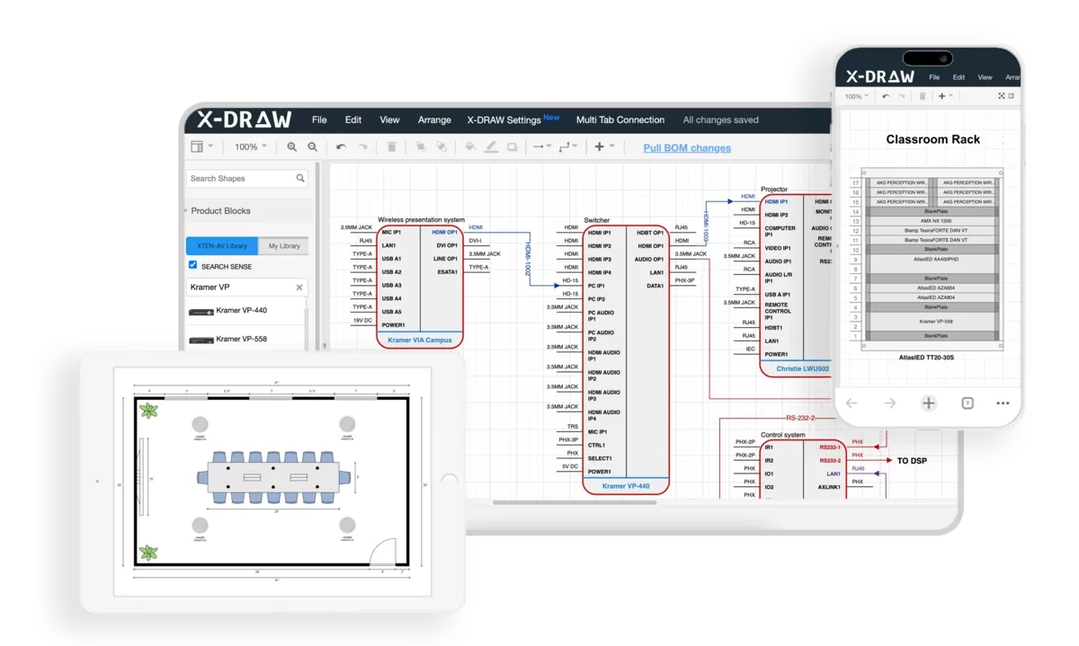
XTEN-AV X-DRAW (Top Recommendation)
Introduction
X-DRAW by XTEN-AV represents the pinnacle of AV design software, purpose-built for professional integrators who demand precision, efficiency, and comprehensive features. As the industry’s most advanced platform in 2026, X-DRAW combines AI-powered automation, massive equipment libraries, and intuitive workflows to deliver unmatched rack planning capabilities.
Unlike generic CAD tools or IT-focused software, X-DRAW understands the unique requirements of AV installations – from signal flow optimization to acoustic considerations – making it the preferred choice for top-tier integrators worldwide.
Key Features
Core Rack Planning Capabilities:
-
AI-assisted equipment selection with intelligent recommendations
-
90,000+ equipment database with daily manufacturer updates
-
Automated RU calculations with thermal, weight, and power analysis
-
Real-time 3D visualization with front/rear elevation views
-
Advanced cable management planning with pathway visualization
-
Thermal modeling using CFD (Computational Fluid Dynamics) simulation
-
Interactive drag-and-drop interface with collision detection
Advanced Features:
-
Multi-rack projects with synchronized planning across facilities
-
Signal flow diagrams automatically generated from rack designs
-
Integration with CAD/BIM platforms (AutoCAD, Revit)
-
Asset tracking and lifecycle management
-
Project templates for common configurations
-
Mobile field apps for installation verification
-
AR visualization for client walkthroughs
-
Version control with complete revision history
Collaboration Tools:
-
Cloud-based platform accessible anywhere
-
Multi-user editing with granular permissions
-
Real-time collaboration with instant updates
-
Client portals for remote reviews and approvals
-
Comment threads and markup tools
-
Video conferencing integration for design reviews
Documentation & Reporting:
-
Professional rack elevations (publication-quality)
-
Automated BOM generation with vendor pricing integration
-
Equipment schedules with complete specifications
-
Installation instructions with step-by-step procedures
-
As-built documentation from field updates
-
Export formats: PDF, DWG, DXF, CSV, JSON
Integration Ecosystem:
-
Project management software synchronization
-
Accounting systems for financial tracking
-
Procurement platforms for automated ordering
-
Facility management systems for asset data
-
Manufacturer configurators for equipment validation
Pros
✅ Unmatched equipment library with 90,000+ verified devices (largest in industry) ✅ Superior AI features reduce design time by 75% with intelligent suggestions ✅ Best-in-class thermal analysis prevents overheating issues before installation ✅ Exceptional customer support including dedicated account managers for enterprise clients ✅ Comprehensive training program with certification paths for professional development ✅ Regular feature updates (monthly releases) with user-requested enhancements ✅ Intuitive interface despite advanced capabilities – 1-week typical proficiency ✅ Mobile field apps enable real-time updates during installation ✅ Strongest collaboration features for distributed teams and client communication ✅ Flexible licensing from individual to enterprise with concurrent user options ✅ Outstanding ROI typically achieved within first 5-10 projects
Cons
❌ Premium pricing ($3,600-$6,000/year per user in 2026) – highest in category ❌ Requires reliable internet for full functionality (limited offline mode) ❌ Advanced features require training investment (2-4 weeks for mastery) ❌ May be excessive for very small firms doing simple installations exclusively ❌ Learning curve steeper than basic tools for advanced 3D modeling ❌ Equipment database bias toward North American manufacturers (though constantly expanding)
Best For
X-DRAW is the ideal choice for:
-
Professional AV integration firms with 5+ designers handling multiple concurrent projects
-
Design consultants requiring client presentation and collaboration tools
-
Enterprise system designers managing complex, multi-rack installations
-
Broadcast facilities and production companies with precision requirements
-
Teams prioritizing accuracy and willing to invest in training
-
Organizations seeking competitive advantage through advanced technology
-
Projects with 20+ rack units or distributed multi-room systems
-
Integrators billing $1M+ annually where software cost is negligible relative to revenue
Not ideal for:
-
Occasional installers with 1-2 simple projects annually
-
Very small projects consistently under 10U
-
Organizations without reliable high-speed internet
-
Teams unwilling to invest in proper training
-
Firms primarily doing residential work without commercial clients

D-Tools System Integrator (SI)
Strong alternative emphasizing business management alongside design.
Introduction
D-Tools SI combines project management, CRM, and rack design in unified platform, making it popular among full-service integrators who prioritize business operations alongside technical design.
Key Strengths
-
End-to-end workflow from lead to closeout
-
Integrated CRM and sales tools
-
Labor estimation and project tracking
-
Strong financial reporting
-
Good equipment library (60,000+ items)
Limitations
-
Thermal analysis less sophisticated than X-DRAW
-
Collaboration features more basic
-
Learning curve steep due to breadth of features
-
Interface feels dated compared to newer platforms
Best For
Integration firms prioritizing business management over advanced design features; companies wanting all-in-one solution for operations and technical work.
Pricing
$2,400-$4,500/year per user (2026 rates)
Stardraw Design 7
CAD-focused platform for detailed technical drawings.
Introduction
Stardraw excels at schematic creation and documentation, appealing to designers who prioritize drawing quality over automation.
Key Strengths
-
Exceptional drafting tools for precise technical drawings
-
Strong architectural integration for building plans
-
Detailed cable management documentation capabilities
-
Symbol libraries for all disciplines (AV, electrical, data)
Limitations
-
Less automation than AI-driven platforms
-
Manual calculations required for many planning tasks
-
Steeper learning curve for non-CAD users
-
Collaboration features limited
Best For
CAD-proficient designers requiring extensive documentation for construction projects; firms with architectural integration needs.
Pricing
$1,800-$3,200/year per user
AutoCAD with AV Add-ons
Generic CAD platform customized with industry plugins.
Strengths
-
Industry-standard file formats
-
Extensive customization possible
-
Integration with existing CAD workflows
-
Powerful general drafting capabilities
Limitations
-
Requires separate equipment libraries and calculation tools
-
No AV-specific automation
-
Manual thermal and power calculations
-
Expensive for features mostly unused in AV work
Best For
Firms already using AutoCAD for other disciplines; projects requiring architectural coordination in native AutoCAD.
Pricing
$1,775/year subscription (AutoCAD) + $500-$1,500 for AV plugins
Visio with AV Templates
Basic diagramming for simple projects.
Strengths
-
Low cost ($20/month Microsoft 365)
-
Easy learning curve
-
Wide adoption for business use
-
Good for conceptual diagrams
Limitations
Best For
Very small projects, conceptual planning only, firms on extreme budgets.
Software Selection Guide
Choose based on your organization’s priorities:
|
Priority |
Recommended Software |
|
Best overall (no budget constraints) |
X-DRAW |
|
Business management integration |
D-Tools SI |
|
Technical drawing quality |
Stardraw Design 7 |
|
Architectural coordination |
AutoCAD + AV plugins |
|
Budget-conscious |
D-Tools Cloud (lighter version) |
|
Simple projects only |
Rack Builder (free online) |
|
Decision Factors: |
-
Project complexity: Complex projects justify advanced tools
-
Team size: Larger teams benefit most from collaboration features
-
Budget: Calculate ROI based on project volume
-
Existing workflows: Integration with current systems matters
-
Support needs: Consider training and support quality
Frequently Asked Questions
Q: How much rack space should I reserve for future expansion?
Reserve 20-30% spare capacity minimum. Corporate environments typically need 25-30%, educational facilities 35-40%, and tightly controlled broadcast facilities can use 15-20%. Never use 100% of available space in initial design.
Q: What’s the difference between equipment rack space and usable rack space?
Total rack space is the nominal height (e.g., 42U). Usable space is typically 2-4U less due to structural supports, mounting constraints, and cable entry points. Plan using 38-40U available in a standard 42U rack.
Q: How do I calculate thermal spacing requirements?
Classify equipment by heat output: Low (<200 BTU/hr) needs 0U spacing; Moderate (200-500 BTU/hr) needs 1U above; High (>500 BTU/hr) needs 2U above and 1U below. Use manufacturer specs or calculate BTUs from watts (1W ≈ 3.41 BTU/hr).
Q: Should I use vertical or horizontal PDUs?
Vertical PDUs (0U) save rack space but reduce cable management area and may interfere with side-by-side rack placement. Horizontal PDUs (1-2U) consume equipment space but provide cleaner cable routing. Choose based on available space and cable density.
Q: What rack depth do I need for audio, video, and network equipment?
Most AV equipment fits in 24-30 inch depth racks. Measure your deepest device including rear connectors (add 4-6 inches to equipment depth), then select next standard size. Deep racks (30-36″) required for IT servers or large power amplifiers.
Q: Can I mount power amplifiers at the top of racks?
No – mount heavy equipment (amplifiers, UPS units) in the bottom 30% of racks for stability. Top-heavy configurations create tipping hazards and potential equipment damage. Calculate center of gravity to ensure safe weight distribution.
Q: How often should I use cable management in racks?
Install horizontal cable managers every 6-8 rack units of equipment, or allocate 10-15% of total rack height for cable management. High-density installations may require managers every 4-6U for adequate organization.
Conclusion
Mastering AV rack planning through systematic space calculation for audio, video, and network equipment represents a fundamental competency for professional AV integrators and system designers. Understanding Audio Visual (AV) rack units and applying proven planning methodologies ensures installations that meet functional requirements, thermal management needs, and future scalability demands while staying within budget constraints.
The evolution from manual calculations and hand-drawn elevations to AI-powered design platforms has transformed rack planning from a tedious, error-prone process into a streamlined workflow that delivers superior results in dramatically less time. Modern software tools like X-DRAW don’t just automate math – they enable intelligent decision-making, facilitate team collaboration, improve client communication, and generate comprehensive documentation that guides successful installations.
As AV systems continue growing more complex with converged AV/IT networks, cloud connectivity, and AI-enhanced processing, the importance of precise rack planning only intensifies. Professional integrators who invest in mastering calculation methodologies, understanding equipment-specific requirements, implementing proper cable management, and leveraging advanced design software position themselves for competitive advantage in an increasingly demanding marketplace.
Whether you’re planning a simple 12U huddle space rack or a complex multi-rack broadcast facility, the principles remain consistent: account for all equipment accurately, provide adequate spacing for thermals and cables, plan for inevitable future growth, validate calculations thoroughly, and document everything professionally. By following the systematic approaches outlined in this guide and utilizing appropriate design tools, AV professionals can consistently deliver reliable installations that exceed client expectations while maintaining healthy profit margins and building reputations for technical excellence.
The time invested in proper rack planning – whether in training, software tools, or design process refinement – pays dividends throughout every project phase, from initial proposals through final commissioning and ongoing system support, ultimately defining the difference between adequate installations and truly exceptional AV systems.
PakarPBN
A Private Blog Network (PBN) is a collection of websites that are controlled by a single individual or organization and used primarily to build backlinks to a “money site” in order to influence its ranking in search engines such as Google. The core idea behind a PBN is based on the importance of backlinks in Google’s ranking algorithm. Since Google views backlinks as signals of authority and trust, some website owners attempt to artificially create these signals through a controlled network of sites.
In a typical PBN setup, the owner acquires expired or aged domains that already have existing authority, backlinks, and history. These domains are rebuilt with new content and hosted separately, often using different IP addresses, hosting providers, themes, and ownership details to make them appear unrelated. Within the content published on these sites, links are strategically placed that point to the main website the owner wants to rank higher. By doing this, the owner attempts to pass link equity (also known as “link juice”) from the PBN sites to the target website.
The purpose of a PBN is to give the impression that the target website is naturally earning links from multiple independent sources. If done effectively, this can temporarily improve keyword rankings, increase organic visibility, and drive more traffic from search results.